Jeffa Autopilot Failure
Printed From: myHanse.com
Category: Hints & Tips
Forum Name: 505/508
Forum Description: 505/508 Hints, Tips and News
URL: https://www.myhanse.com/forum_posts.asp?TID=10801
Printed Date: 27 March 2026 at 03:29
Software Version: Web Wiz Forums 12.06 - https://www.webwizforums.com
Topic: Jeffa Autopilot Failure
Posted By: kipwrite
Subject: Jeffa Autopilot Failure
Date Posted: 31 May 2018 at 02:02
|
My Hanse 505, #123, equipped
with a Jeffa DD1 autopilot (photo below) suffered a jammed autopilot motor that
locked the steering a few weeks ago in the Gulf Stream. This rendered my 505 not under command. I took delivery in May 2016 and
weve sailed over 9000NM since, between Maine and the Bahamas. Shes just a
fantastic vessel, and Ive gotten fabulous support from my dealer. The Jeffa autopilot had been
perfect until it failed. We departed the Treasure Cay, Abacos, Bahamas for Cape Charles, VA the evening of May 4, with the support of Commanders Weather. Roughly 36 hours later we were in the Gulf Stream, sailing NE, in a 7-10 foot, long-period following sea, with ~25kts of wind from the SE, with 2nd reef main, and a bit of Genoa out. She was surfing beautifully. The autopilot sensitivity was set on 3, the middle setting, where it has been set since the boat was delivered. An alarm sounded on the autopilot, and the helm was immobilized. No amount of effort could turn the rudder. The standby button was inoperative. Powering down voltage at the Wurth panel had no effect. A fuse on the panel had blown (replacing this fuse later had no effect). We sheeted in the main and rolled in the Genoa, and then removed the floor panel above quadrant. The quadrant and cables and cable tension all looked good (and had previously been regularly inspected and properly tensioned.) Suspecting a jammed autopilot motor, we removed the bolts connecting the autopilot ram to the quadrant, and then removed the ram, which allowed us to regain control of the helm. This entire operation took perhaps twenty minutes. We were soon in touch with Jeffa Denmark. After hand-steering all the way back to Stamford CT, our final destination, the autopilot was removed and shipped to Jeffa in Denmark for inspection. A few days ago Jeffa reported There has been an overload on this drive and this caused a damage on almost all gearwheels. The big gearwheel, big shaft, complete gearwheel shaft must be replaced. There was no evidence of water damage to the motor. A few observations about this incident: 1. The drive may have been overloaded, but at no time had this boat been sailed in conditions even approaching its design envelope. 2. 2. The autopilot motor had previously worked perfectly. It gave no warning prior to failure, made no unusual sounds, and never went into a standby mode, prior to failing and jamming the helm. No fuse had previously blown. It simply could not have operated any better, until it failed in a way that could have easily resulted in fatalities, under other circumstances. 3. 3, My crew and I were
lucky a) we were able to sort out the issue quickly; b) we were not in an
active seaway or near land, and c) our sail plan, the winds and the sea state
were such that we werent put in danger by our sudden loss of steering. 4. I understand
things can and often do break on our boats, but a failure that renders an
immediate loss of steering, while the boat has been consistently operated
within its engineering design envelope, and carefully maintained, is not a
failure Im interested in experiencing again. I declined the offer from Jeffa to rebuild this autopilot motor. Hydraulic autopilots, as I understand things, will return to standby mode under failure. The Jeffa DD1, replete with gears, locked the steering under this failure scenario. I had received no warnings or advice prior to this episode that DDI should not be used offshore for an extended period of time, or that it might be subject to this kind of locking failure. I have no reason to believe the DDI would not fail again, if used similarly. Ive asked my dealer to install a beefier hydraulic autopilot, with a design and failsafe that releases the helm under failure mode. My suggestion to my fellow 505 owners is: at minimum, be aware of this potential failure, and familiarize yourselves with how to remove the autopilot ram quickly, should the need arise. Speaking for myself, I'm unwilling to sail with this electro-mechanical Jeffa autopilot motor going forward. Im
also curious if anyone else has had a similar occurrence?
------------- Kipwrite |

Replies:
Posted By: Alesea
Date Posted: 31 May 2018 at 10:02
|
Thank you very much for your comprehensive post and bringing this to everyones attention. We also have a 505, but have not experienced or heard of this particular issue. We are crossing the Atlantic later this year and having heard several stories of autopilot steering failure are in the process of installing a hydrovane. ------------- Alesea Hanse 505 NZL9464 |
Posted By: Brufan
Date Posted: 31 May 2018 at 10:35
|
As far as I know DD1 drive is designed for yachts up to 45 feet. Strange that HANSE use this drive on a 50 feet yacht !!! So that could be the main reason why it has been overloaded and failed. I do have the same drive on my 35 feet (6,5 tons empty - 8 tons loaded). Except water ingress I had no issue with it since 7 years. ------------- Bruno hanse 355 - 57 S/Y Spicy Ginger White hull, 2 cabins, Volvo D1-30, Selden rig, removable mainsheet track system, Simrad (now B&G)-Jefa autopilot. |
Posted By: Rubato
Date Posted: 31 May 2018 at 17:55
I was going to say the exact same thing. The DD1 is used on my 400e as well. I've taken one apart and while I'd say it's robust there is no way I would think it appropriate for a dual helm 50 foot boat. I feel this is another case of Hanse cost cutting and pushing gear to their working limits and beyond - I've had to upgrade blocks, halyards, sheets, sheaves, and winches over the years for the same reason.... Back to your issue, looks like you came to the same conclusion I would have in your place - replace the unit with something more appropriate. Glad it failed in a non hazardous situation for you and everyone and the boat is fine Good luck. Steve
------------- Steve Hanse 400e, #168 |
 Brufan wrote:
Posted By: 415 Singapore
Date Posted: 01 June 2018 at 15:04
|
Hi we have a DD1 on our 415 too, they can also fail in the jammed position if the autopilot computer fails. We had a new computer installed and they incorrectly wired the power supply which ruined the computer. Next time we tried to leave the marina, the rudder was locked, fortunately I had tried the helm before leaving and more fortunately this didn't happen at sea. I admire your logic and seamanship in resolving the problem Good luck Paul ------------- Paul - Night Train - 415 #136 |
Posted By: kipwrite
Date Posted: 06 June 2018 at 11:35
|
This morning I received a note from Jefa with an important update on my autopilot failure, that should be shared with other owners: We have had a look at the picture below and can see that the draglink is mounted in a wrong hole on the tiller arm on the quadrant, it will for sure weaken the drive a lot. This was likely a build error as I never moved the drag link, and the autopilot was never serviced. Id recommend checking to assure your drag link is mounted to the outer hole on the quadrant. Ive pasted below an enlargement of the area of the quadrant in question.  ------------- Kipwrite |
Posted By: chillios
Date Posted: 07 June 2018 at 22:05
|
Hi Kip, Though I have not had a similar lockup of our autopilot (I've alway's been able to place my unit into standby), after a recent upgrade of our B&G gear, I did have 2 separate planetary gear failures. The error in our case was determined to by an error in the max rudder angle setting on our new Zeus plotter. I'm happy to say that the autopilot worked well on our recent trip from BVI to Newport via Bermuda. I will definitely take a look at where our autopilot is connected to our quadrant. If you find a more robust autopilot that would fit in our limited space, please let us all know. I for one would be happy to upgrade this unit. Thanks again for the great writeup. -Chris |
Posted By: STEVE MCINNIS
Date Posted: 08 June 2018 at 01:53
|
Checked our autopilot, it's connected correctly in the outer hole. S |
Posted By: High Time
Date Posted: 11 June 2018 at 16:19
|
I've just checked High Time (415) and the drag link is connected to the inner hole. Curiously I also blew the 10A in-line drive motor fuse last week, after 6 years of faultless operation. I was making a number of +10 adjustments while motoring so I suppose that could have caused a temporary overload on the motor working against the prop wash, especially if the drag link is in the wrong hole. The steering in manual mode is, as always, light and positive so no change there. It is easy to move the drag link to the correct hole but what is involved in re-setting up the autopilot geometry in the AP24 etc? Can you just use the autotune facilities or do you need to enter any (new) stuff manually? ------------- Roger High Time (415 #038) |
Posted By: Rubato
Date Posted: 12 June 2018 at 07:24
|
Not sure you have to do anything at least to start with. The autopilot uses the rudder feedback sensor to understand the position so it will provide "drive" to the rudder until the feedback sensor arrives at the correct position just like always. ------------- Steve Hanse 400e, #168 |
Posted By: High Time
Date Posted: 15 June 2018 at 13:33
|
Hi Steve On thinking about it, if you change the drag link mounting point on the rudder quadrant you are changing the length of travel of the rudder feedback unit. This was calibrated as part of the original commissioning dockside set-up process when the drag link was attached to the inner fixing point. I had to dig out my copy of the AP24 Operators Manual to see how to do this. It's actually quite simple - effectively just turning the wheel to the end stop on starboard and port and resetting the zero point (since I had slightly turned feedback unit to better align with the draglink. The rest of the commissioning set-up parameters don't need changing. The DD1 is now driving the rudder on the outer fixing hole, which should reduce the load on the motor slightly. I haven't tried it at sea yet but it all appears to work fine at the dockside. I'll report again if there are any problems 'at sea'. ------------- Roger High Time (415 #038) |
Posted By: fulanito
Date Posted: 17 June 2018 at 03:38
|
Thanks Kipwrite for taking the time and effort to share this incident which could have had a potential deadly outcome. The DD1 motor is stretched beyond its limits for a 50ft loaded vessel. I believe that it has been incorrectly "sized" to operate above the SWL using a calm to moderate seas rudder loading scenario. Hanse is launching a new 508 model (same haul- new deck) in the next couple of months. It will be interesting to see what AP will be used. Cheers GG
|
Posted By: KiaOraSailor
Date Posted: 17 June 2018 at 08:54
|
Hi Kipwrite, I'm new here in this forum and your post had triggered me to contact Jefa in Denmark about a similar problem that we encountered on our H505 #92. Autopilot drive failed recently. The support by Jefa was superb - after few hours I received detailed response by their technical lead on that, including drawings and results from discussions with Hanse designers. Their statements were mainly: 1) the DD1 ist NOT undersized for the 505 (misleading statement on their website, and the 505 has rather low rudder forces for a 55ft boat - yes, I would agree!) 2) it is important to install the drive correctly: "We have talked about your case here internal, and have may be a clue what could be the reason on the failure of the drive unit. Please look at the attached buildcard on part no.6, the draglink from the drive to the tillerarm on the quadrant. Please check that your draglink is mounted in the outer hole as on the buildcard. And not in the inner hole I could expect was done. It will give a much stronger drive, and are constructed for that." So, when looking at your photo this is/was not done on your boat... have you meanwhile checked or changed? This is from their buildcard: 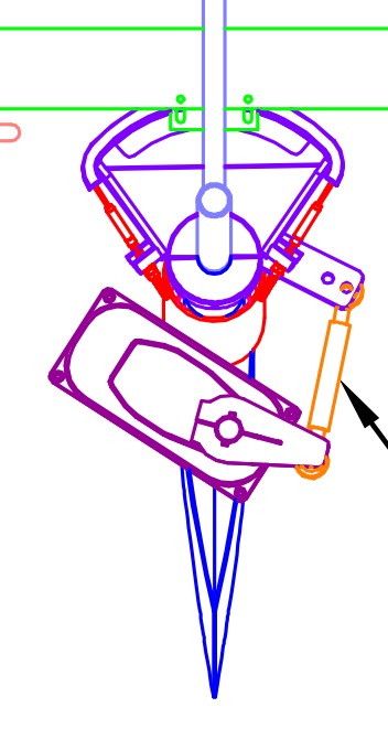 Good luck Walter |
Posted By: kipwrite
Date Posted: 17 June 2018 at 17:10
|
Walter Thanks for your note. Im very curious to hear about how your Jeffa unit failed, and if it jammed the helm. Was your drag link mounted to the wrong hole as well? In the end I had my DD1 unit repaired and reinstalled, and the drag link is now mounted on the correct, outer hole on the tiller arm as shown on the build card. My intent is to use the DD1 a back up unit to a linear hydraulic drive I will use as a primary. It appears I may have to add a mounting point on the quadrant to get this larger hydraulic unit to fit. Theres not quite enough room for any of these to fit into the tight space and connect to the tiller arm. Curious if anyone out there had tackled this? Once this is all sorted I will post photos. ------------- Kipwrite |
Posted By: KiaOraSailor
Date Posted: 23 June 2018 at 18:47
|
Hi Kipwrite, Luckily the drive did not jam the helm in our situation and I can't even tell you how it failed since this had happened to a charter crew ... and I still don't know about the root cause. Meanwhile the unit is repaired and back on board. The technical crew confirmed that the tiller arm connection was correct before. I will still try to rely on the design and give it a second try. Will keep you updated here. Cheers Walter |
Posted By: Rubato
Date Posted: 25 June 2018 at 17:28
Roger, of course you are right. I was a little too quick in my response keying on the term "rudder feedback unit". As you pointed out, it actually isn't connected to the rudder, it's connected to the drive (should be called drive feedback unit :) ) and thus calibration is definitely needed. ------------- Steve Hanse 400e, #168 |
Posted By: Samtutuki
Date Posted: 26 June 2018 at 02:40
|
My latest model 315 also has a DD1. In spite of Jeffa and Hanse saying DD1 can handle a 50 foot boat I am "impressed' that what is good enough for a 315 is also good enough on a 505!!
|
Posted By: KiaOraSailor
Date Posted: 17 July 2018 at 17:28
|
Hi Kipwrite, Finally I can give you a short statement about what was wrong on our autopilot drive. However, it's not much to report, but our tech crew told me that "... The graphite contact pins were twisted (or in wrong position?) which had blown the fuse. So the contact pins and fuse were replaced and the entire unit overhauled..." No pictures of the damage available, sorry. I remember that we always felt quite unusual vibrations on the steering wheels when running on engine - even with much less than normal speed. So, I considered that these permanent vibrations might have had impact back to the AP drive? But under sails everything fine and no vibrations. Has anyone made similar experience? Perhaps caused by the folding prop? So I got back to Jefa with that info and idea but they neither have a clue of the root cause for the AP failure nor believe that it might have been the vibrations in the steering system. |
Posted By: jdderijke
Date Posted: 29 December 2018 at 16:14
|
Well.....I had the exact same problem with my Hanse 505 #114... On our trip from the Cape Verde Islands to Grenada 2 weeks ago. In the middle of the night (and about 80 miles out from Mindelo) our DD1 failed and locked the steering completely. We also removed the connection between the quadrant and the drive unit and thereby regained control of the rudder. We hand steered back to Mindelo and contacted Jeffa. Support was good, but it was almost impossible to get parts send to the Cape Verdes in time. So we took apart the drive unit and discovered that 3 teeth broke off from the central planetairy gear axle. The reason the system locked was that 1 tooth fell down between the housing and the gear and locked the gear, while the other 2 where kept inside the gearwheel by grease and simply had no room to fall down. We had a machine shop weld new teeth on the gearwheel, tested it and tested it again, and left for our second try to cross the Atlantic. After about 1 week, we heard a bang, but the pilot continued to work. We disassembled the pilot and found another broken tooth (one of the welded ones). We decided to handsteer the rest of the crossing to Grenada, over 1000 miles. In Grenada we received a new central planetairy gear axle and mounted it, and we rotated the central drive axle 180 degrees. My analysis is as follows.... With a well balanced sail plan and because the rudder is balanced, the rudder always performs within 1-3 degrees off the central position, this translates into 2 or 3 teeth on the central planetary gear axle. When the boat is going on a broad reach (150 TWA, 130 AWA), and starts to surf down waves...the rudder can actually push VERY hard against the drive unit (not the other way around), also putting all the force on these 2 or 3 teeths. After 7000 miles of action they simply started to break, 1 by 1. Because there is not much space there, the broken teeth stayed in place, and the only thing you would notice is a soft bang every now and then.....untill the rudder reaches a more extreme position....around 10-12 degrees off centre, and then one of the broken teeth fell down in a little cavity under the gear and locked everything.... Moving the connection on the quadrant more to the outside will reduce the forces that are send back from the rudder to the drive unit, so that seems like a good idea to me.......however, the DD1 may be ok for the Hanse 505 balanced rudder forces in normal operation....but surfing down waves will destroy the gears.....even when you move the connection point on the quadrant to the outside. I suggest also to rotate the gears (central drive axle and central planetary axle) by taking off the drive arm from the unit, and mounting it upside down. Thereby rotating the central axle 180 degrees.... I will investigate further and decide later if i keep this unit or replace it with a T2 hydraulic system... JD, SY Privateer  The central planetairy gear axle with the broken teeth..... 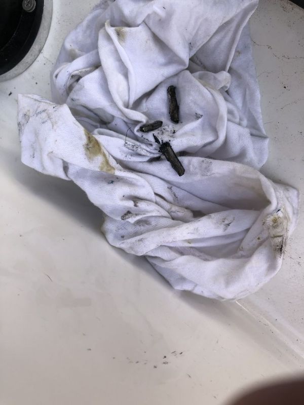 ------------- JD |
Posted By: kipwrite
Date Posted: 29 December 2018 at 16:43
|
Thanks for this thorough report. Your analysis sounds correct. But Im confused by your suggestion in favor of turning the drive arm upside down. Can you clarify? With respect to fitting a larger drive, between my dealer and I we could not locate an alternative to the dd1 that would fit in the space. I installed a Hydrovane, and Im trying not to use the Jeffa autopilot when seas are up. Was your autopilot installed in the correct hole on the tiller arm? ------------- Kipwrite |
Posted By: jdderijke
Date Posted: 29 December 2018 at 22:16
|
Hi Kipwrite. The DD1 has a drive axle with a big gear on the bottom and an arm on the top. Since this axle only turns about 15 degrees both sides (max rudder limit), only a small portion of the gear is ever used. When replacing the central planetary axle (which drives this big gear of the drive axle) or just as a precaution, i think it is wise to rotate the drive axle in order to use the untouched part of the gearwheel. The way to do this: Take off the arm, remove the 2 connections on the arm(one for the rudder indicator and one for the push/pull rod) and remount them on the OTHER side of the arm. Now turn the arm upside down and reassemble and ...... bingo ..... the drive axle will have rotated 180 degrees. I think by doing this regularly one could limit wear of the gearwheels. Yes my pushrod was also mounted to the wrong position on the quadrant, but i left it that way, i dont think it will solve the problem with waves coming from behind.....the forces are simply way to big for 2 or 3 teeth to withstand them.... About your remark for a replacement drive....what do you think about the T2 drive unit? See link https://www.bandg.com/bg/type/autopilots/autopilot-drive-units/hydraulic-ram-t2-12v/" rel="nofollow - https://www.bandg.com/bg/type/autopilots/autopilot-drive-units/hydraulic-ram-t2-12v/ JD, SY Privateer
------------- JD |
Posted By: Samtutuki
Date Posted: 30 December 2018 at 00:52
|
Good and interesting report. Thank you. My view is that the DD1 drive is too small for a 505. According to this Jefa website: https://www.jefa.com/steering/steering.htm boats with an LOA of 40 to 55 feet should use a DD2. Of course there may not be enough space to hold a DD2 but the failure you describe is clearly an overload which should be expected using a DD1 on a 505. My little 315 uses exactly the same drive. Why do Hanse persist in undersizing gear be it anchor windlass or autopilot drive? I think we can all work out the answer$? Perhaps Hanse could offer heavier gear as an option for this intending to do some serious bluewater sailing.
|
Posted By: KiaOraSailor
Date Posted: 30 December 2018 at 11:43
|
Wow, first of all congrats and thanks to jdderijke: once you've figured out it seems to be that easy!  I would like to share two things with you all: 1) root cause of failure: I'm now absolutely sure what had happened on our drive unit last year and what they did for repair: they replaced the broken wheel. And that will happen again unless I will also rotate the configuration as described. However, what should constructors basically change in the design here? Most of the job will ALWAYS happen on those poor 4 teeth! And there is no "idle" function that might allow the unit by itself to rotate the shaft periodically. But such a feature would - ideally - only extend the time to failure, but not prevent the failure. In my opinion, the only effective measure is NOT TO USE the AP for longer time with big waves from the back. Since I believe that such operating mode is just out-of-design-spec. 2) About the DD2 option and the "undersized gear" statements quoted recently: Jefa sincerely claimed that the DD1 is not undersized for the 505 (although they did not comment on special wave conditions). And they also explained to me, that the DD2 is not applicable here since (a) too big and (b) not watertight (!). Maybe, Hanse should just tell the owners frankly that this AP is not designed for bluewater application with days of surfing big waves from the back. It should be considered as temporary tool for steering - especially when running on engine. Long-distance legs should be still a matter of wind vane systems - or perhaps very robust hydraulic AP Systems. BTW: the most efficient test crews for durability of boating gear are the charter sailors. Any design flaws will be unveiled after max. 3 charter seasons.
 |
Posted By: Samtutuki
Date Posted: 30 December 2018 at 21:09
|
Hi KiaOraSailor, I also spoke with Jefa when looking at a second hand 505 and the person I spoke with said something similar. So my followup question to them is if the DD2 is not waterproof and too big why manufacture and sell it? The torque figures also speak volume sunny view DD1 rated torque 150 kgm DD2 rated torque 375 kgm |
Posted By: kipwrite
Date Posted: 30 December 2018 at 22:15
|
Jdderjke- Thanks for the clairificafion. I liked the B&G hydraulic drive you linked to - but it will not fit in the space available on my 505 #123. Jeffa absolutely maintains that the DD1 is appropriately sized for our boats. In my failure, they blamed the issue on the mounting in the wrong tiller hole, so Ive switched mine. I would recommend following their advise. Its an easy fix and will lessen the chance of another failure. If anyone finds a hydraulic unit that fits please let us all know. Otherwise I believe a Hydrovane is the best solution. ------------- Kipwrite |
Posted By: KiaOraSailor
Date Posted: 31 December 2018 at 11:15
|
Hi Samtutuki, I guess the answer to your question is simply: while the yachts were growing bigger and bigger they kept using the same drive unit - and because of the location underneath a simple cockpit cover it had to be waterproof. (maybe this requirement is also a result from the current designs with open sterns? Older yachts such as Sun Oddysseys from before 2009 have the AP drive unit in a sheltered compartment where there is no need for being waterproof). The DD2 looks like coming from another application with different spec for bigger yachts. What I'm curious about now is: Hanse just lauchned the "next" 505 which is the 508 and it will be interesting to see what kind of gear (AP, BT, windlass) they might have upgraded due to our negative experiences? There is one thing I already know for sure: The new swimming ladder on the platform looks much better and adequate now! Cheers and Happy New Year to all Walter
|
Posted By: Alesea
Date Posted: 31 December 2018 at 14:23
|
Jdderjke - thanks for the post and valuable information. Were checking our teeth. We have just crossed the Atlantic with the ARC and had a hydrovane fitted to ease the burden on the autohelm. After two days of part use with quite steep following seas with a cross swell (conditions we now read not recommended for the AP) the bolts attaching the bottom bracket sheared off. We know of a few others who experienced the same problem. Our impression was the hydrovane struggled to correct when what is a very wide transom gets picked up and thrown around. At the time, the boat was well balanced, sailing with a poled out headsail and no. 1 reef in in 20knots of breeze. Admittedly we are new users and may need to adjust the system, but we cant really see a solution for the back of the boat being swung around. Funnily enough (or should I say thankfully) we went back to the AP and it was fine. ------------- Alesea Hanse 505 NZL9464 |
Posted By: tobo2
Date Posted: 23 April 2019 at 08:41
|
As Hanse is boosting the new 508 as a "true bluewater yacht" this AP drive unit should stand harder conditions than only island hopping cruises. I'm sure someone with a 508 can find out (there are about 25 built so far). The same undersizing tendency you can meet with the windlass. A 1000W unit is just not enough for a 15 t yacht! This would be the first thing I would exchange to a 1500-1700 W unit. Why not offering that as an option! |
Posted By: fulanito
Date Posted: 01 May 2019 at 11:42
|
For those interested in replacing the Jeffa DD1 there is an alternative with electro-hydraulic drive that can be fitted just... in the AP cavity. it has a bypass to regain steering control when on standy by or failure. Have a look if that interest you. https://www.pyiinc.com/ls/hydraulic-linear-drives.html" rel="nofollow - https://www.pyiinc.com/ls/hydraulic-linear-drives.html Cheers GG
|
Posted By: kipwrite
Date Posted: 06 May 2019 at 13:42
|
If you could post a photo of this unit installed Id be most grateful.
------------- Kipwrite |
Posted By: colinc
Date Posted: 08 May 2019 at 14:20
|
Being a new owner of a second-hand Hanse 505 I read this thread with interest. Checking the drive the link is set to the innermost hole and not the outer one. Before switching to the outer hole as suggested in this thread I did some measurements and compared them to the Jefa installation guide for the DD1 drive. I am not sure it is wise to make such a change. On my boat moving to the outside hole makes the DD1 drive rotate +- 72 degrees to give the maximum rudder of +- 36 degrees. The inner hole (were it was installed) makes the DD1 drive move +- 55 degrees for the same rudder travel. Looking at the Jefa guide the DD1 is designed to operate over maximum of +- 65 degrees. So in the outer hole this is straining the drive beyond its design whereas the original hole is only using 85% of the available rotation. In my mind to slightly underuse the drive is better than overextending it. There are several factors that are at play here not least the position of the drive and the length of the drive actuator (as well as the position on the rudder actuator). If you look at the Hanse build card the drive is placed diagonally across rather than straight fore and aft as on mine (and the pictures in this thread). The key is not the angle but the offset between the rudder and drive centres. Jefa recommend 106mm or greater for this offset as appears to be the case on the buildcard. My offset is MINUS 50mm. So the positioning of the drive is completely different to that build card. As such it isnt a reliable indicator of which hole is best to be used. Also if the outer hole is used then the link will need to be adjusted in length. On mine it would have to be shortened to use the available +- 65 degrees equal on both port and starboard. Otherwise the overextending would be significantly worse on starboard. One could also reduce the problem of overextending by cutting the maximum rudder angle in the autopilot setup. I plan to go to Jefa to ask about this. Has anyone else done this already? That is to supply Jefa with the exact measurements of the actuators and positioning of the drive to get their best advice? I am not so upset about using the DD1 as other commentators. Key is not the length of the boat but the torque needed to turn the tiller. The DD1 gives 150kNm which I think is plenty for this boat. I certainly never need to apply anything like that when hand steering - indeed it would be hard to do so. Even using just 85% of that is still plenty. However checking the right geometry of the DD1 installation is pretty important. I think asking Jefa is best. Has anyone done this? |
Posted By: kipwrite
Date Posted: 09 May 2019 at 22:22
|
Im not sure I followed all that, but I can confirm both Jeffa and my dealer recommended using the outer hole, as shown in the build card previously posted. Im not sure the maximum rudder limit issue you referenced comes into play. In most use cases the rudder angle is less than 10 degrees when the autopilot is engaged. Since installing the rebuilt DDI about 11 months ago it has worked well, with two passages in excess of 900 miles crossing the Gulf Stream, and a shorter trip up to Maine and back (from CT). . I have made the following adjustments in my use of the autopilot: - I keep performance set to 1. This puts less pressure on the system, saves power, and doesnt seem to effect performance in any noticeable way. - I hand steer when in steep (6-7+) following seas, or try to get the boat balanced so I can use the Hydrovane. This isnt always possible, as Im still learning how to use it. - I try to use the Hydrovane when possible to give the DDi a rest. Sailing with the Hydrovane has made me more sensitive to keeping the boat well balanced. This also eases the loads on the DD1. While Id much rather have a hydraulic unit, Ive yet to find one that fits into the space allotted. If you get further detail from Jeffa Id be interested in hearing about it. SV Lilia Slot 123 ------------- Kipwrite |
Posted By: Captain Cook
Date Posted: 09 May 2019 at 23:08
|
The Jefa homepage delivers a lot of information. Try it. And if you are a new member, share your boats name and build # with us. The 370 and 400 uses the inner hole of the DD1 uploads/729/JEFA_steering_Hanse_400-2005-2007.pdf" rel="nofollow - uploads/729/JEFA_steering_Hanse_400-2005-2007.pdf UPDATE: I am referring to the inner hole on the arm of DD1, I just noticed on page one of this thread, that there are 2 holes in the other end of the connecting rod. (Not the same layout as on my boat). In the aforementioned picture on page 1 there is only one hole in the arm of DD1, simply because it is common practice to saw off the outer hole when it is not in use. Jefa is an extremely customer-friendly company which answers both e-mail and telephone requests in a quick and professional manner. : END OF UPDATE.
------------- Freya H400 #27 (2006),2-cabin, 40HP 3JH4E, 3-blade Flexofold, Aries LiftUp Windvane, Exturn 300, Jefa DD1,Simrad NX40,Icom M603(VHF)+M802(SSB) |
Posted By: Sea-U
Date Posted: 10 May 2019 at 09:55
|
There was another thread where the inner part of the DD1 was worn out. The outer hole was used and put too much stress to the DD1..... as I remember. -------------  Sea-U is a 370e #532 located SW Norway Sea-U is a 370e #532 located SW Norway
|
Posted By: JUTTER
Date Posted: 10 May 2019 at 11:37
|
It is quite confusing to talk about inner/outer hole without specifying output arm or tiller arm. After reading again different posts, also in other threads, about the DD1 APdrive, this is what I understand.
Jefa insists on connecting the drag with the inner hole (130mm) of the output arm of the drive. But on the tiller arm they prefer to connect the drag with the outer hole. Anyway, that is how I read the different texts. Claude ------------- JUTTER, Hanse 350#0256, 2010, deep keel, Zeeland |
Posted By: Sea-U
Date Posted: 10 May 2019 at 13:58
|
This is mecanics. The least load/wear for the DD1 is applied with the inner hole on DD1 and outer hole on tiller arm. Change one or both gets more travel and higher load for the DD1. ------------- Sea-U is a 370e #532 located SW Norway
|
Posted By: colinc
Date Posted: 10 May 2019 at 19:10
|
Hi all. I have a new user account as I lost access to the old with an email change. I have recently upgraded from a 370 to a 505 (hull #067) called Air Speed. Just sailed her from Malta to Corfu and planning to sail around the Ionian this year. Great boat. The Jefa setup is best explained in their specification form at https://www.jefa.com/ftp/steering/forms/Direct-Drive-Spec-Form.pdf" rel="nofollow - https://www.jefa.com/ftp/steering/forms/Direct-Drive-Spec-Form.pdf On my boat the Output Centre is 130mm. The Tiller Centre is either 165mm or 200mm (AKA the inner and outer holes). From the specification we should use the outer hole at 200mm. BUT (a big but) my offset distance is MINUS 50mm. If should be PLUS 106mm as in the Jefa form. That means the drive is using the tiller over a different arc that changes the geometry. My measurement is that it takes the maximum rotation required by the DD1 to about 72 degrees - certainly beyond the 65 degrees it is designed for, The install instructions are explicit that the drive must not the extended and that buffers are fitter to the tiller to prevent it. So why is the offset minus? A mistake? If not a mistake then presumably the inner hole should be used to not over extend the drive. Or do we need to refit the DD1 drives with the correct offset? The build card has the drive fitted differently and appears to use the correct positive offset. That would fit with use of the outer hole. I will take this up with Jefa and report back. In the meantime I will stick with the inner hole. I will post a picture of my installation in case yours is different.
|
Posted By: colinc
Date Posted: 10 May 2019 at 19:20
|
Actually my picture is too big to upload and I sm using an ipad. However it is the same as the pictures earlier in this thread. The DD1 is placed with the long length fore and aft and the centre offset to the port side (and hence a negative offset). To be positive it would have to be placed on the starboard side. |
Posted By: kipwrite
Date Posted: 10 May 2019 at 22:13
|
Im fairly sure there was a Jeffa DD1 build card specific to the 505 included in the documentation I received when the boat was delivered new. Ill see if I can find it and will scan and post.
- FYI, the six page Jeffa document that came with my boat at delivery shows the same configuration found on the Jeffa site, and does not match the in-line set up we have on our boats, as shown in the photos on page 1 of this thread. Its signed by a Jeffa engineer. Theres an alternate installation shown but nothing like the fore-aft set up we have. Interesting to hear what Jeffa has to say. ------------- Kipwrite |
Posted By: ohthetrees
Date Posted: 24 November 2019 at 09:42
|
I just bought Hanse 505 hull #115. and am feverishly prepping to hand off to a delivery crew. The http://www.cruisersforum.com/forums/tags/boat.html" rel="nofollow - boat is impeccably maintained, and was actively cruised by the owners when I bought it. In researching known problems with the 505, I came across this thread. My new boat has the link arm in the wrong hole. In fact, the owner had the same failure, had the auto pilot repaired (but when it failed it did not lock the steering), but didnt get the memo about relocating from the inner to the outer hole, so it is still in the improper location. I attempted to move the link arm from the inner to the outer hole, but I failed. There are two holes in the lever arm. I thought it would be a matter of unbolting the through bolt from the link arm to the lever arm, and moving it over to another hole. However there appears to be a stainless (?) http://www.cruisersforum.com/forums/tags/steel.html" rel="nofollow - steel bushing , Which I think is pressed or friction fit into the hole in the aluminum lever arm. I was not able to remove this bushing with pretty big vice grips, despite http://www.cruisersforum.com/forums/tags/heating.html" rel="nofollow - heating the http://www.cruisersforum.com/forums/tags/aluminum.html" rel="nofollow - aluminum lever arm, and cooling the bushing with ice. If anyone has gone through this, I would be very grateful. I would love to have this fixed before my crew took the boat across an ocean.   |
Posted By: colinc
Date Posted: 25 November 2019 at 07:27
|
That pin should just come out. Looks like it has corroded a little and jammed in. However dont panic. IMHO the connector is in the correct hole. Moving to the outside one will make the Jeffa drive move further than it is designed to. although it will also reduce loading. I dont think it is at all clear which is best. If your system has been working fine for some time (and the jammed in connector indicates it has) IMHO you would be advised to leave it alone. Or check yourself with Hanse or Jeffa. If you do move it you will need to retune the steering settings in the B&G autopilot. Repeat the sea trial section.
|
Posted By: ohthetrees
Date Posted: 25 November 2019 at 08:35
|
previous owner had the gear stripping failure, but didnt move part, so Im not feeling great about leaving it. While moving location would reduce stress close to center, I agree stress would increase at extremes. My idea for mitigation is to do the dockside lock-to-lock calibration, but rather than going from -46 to +46°, I would trick the autopilot by only going from -30 to +30 during the calibration. Then autopilot would think that is where the stops are. I think it is pretty rare for autopilot to command more than 10 or 20 degrees anyway. If it is trying to command >30° I have other problems.
|
Posted By: colinc
Date Posted: 25 November 2019 at 09:13
| That is a good idea. We have had the connector in the inner hole for five years without problems. But all in the Med so no ocean surfing. Will use your idea to switch though. These rudders are suoer powerful anyway. |
Posted By: jdderijke
Date Posted: 25 November 2019 at 12:54
|
Please let me know how to remove the pin. I also cant get it out. I am replacing the DD1 drive with an hydraulic one and need to move the pin to the underside of the quadrant..... is the pin crimped in? Or is it threaded in? ------------- JD |
Posted By: ohthetrees
Date Posted: 26 November 2019 at 08:27
| I hope someone who knows for sure can answer. I dont yet know. |
Posted By: colinc
Date Posted: 26 November 2019 at 08:50
|
I have just taken mine apart again to confirm. That pin should come up out of the hole it is in. No thread just a push fit. It is held in place by the bolt holding on the linkage (which you have already removed for your picture). As I said before, your pin must be ceased in. |
Posted By: colinc
Date Posted: 26 November 2019 at 09:02

|
Posted By: ohthetrees
Date Posted: 26 November 2019 at 15:55
| Thank you. Confirmation that the pin is not threaded is very useful to me, and it will give me confidence to do the puller approach. |
Posted By: fulanito
Date Posted: 13 December 2019 at 08:06
|
pin is stainless steel and arm is aluminum therefore there is galvanic corrosion in the arm. Aluminum has expanded and locked the pin. Anti corrosion grease will be required to stop it from being corroded
|
Posted By: ohthetrees
Date Posted: 13 January 2020 at 05:42
|
Hello all. I thought I would report an interesting email correspondence I had with Jefa. Excellent support as usual. They asked me not to directly quote the email so as not to ruffle any feathers with Hanse. Here are my takeaways from the correspondence. 1) The drag link should definitely be attached to the outer hole in the tiller arm. 2) The "pin" that in my case seem corroded in place can be ordered with part #TLJPIN16 3) The different mounting geometry that hanse chose to mount the DD1 unit (centerline rather than at an angle) compared to the build card is not a concern. 4) They have heard of no failures of DD1 mounted in the correct hole. Saving the best for last, they have developed a mounting solution to install a DD2 in the 505 for another 505 owner. It involves a secondary conical bored tiller arm attached the the rudder post below the deck, and the DD2 is mounted upside down below the deck. The existing quadrant, tiller arm, (and DD1?) can be left in place. I am very interested in this system as the mechanical system has a number of advantages over hydraulic, and the DD2 has much more power (375kgM vs 150kgM for the DD1). I'm awaiting pricing on a kit that includes all Jefa parts necessary, and (I think) reinforcing backing plates for mounting the DD2. You may have seen from another thread that my DD1 did (probably) fail during the delivery to Hawaii with a delivery skipper. The link arm was in the wrong inner hole at the time. At this time I'm undecided whether to replace with a DD2 ($$$) or, considering they have not heard of failures when mounted in the outer hole, repair the DD1 and give it a try with the link arm attached properly.
|
Posted By: colinc
Date Posted: 13 January 2020 at 06:00
|
Thanks for that info. I am sure of interest to all 505 owners. On the option of keeping the DD1 do they recommend how to go about moving to that outer hole? 1. Reducing the angle through which the rudder operates so not taking the drive too far either end 2. Changing the length of the push rod so that the middle rudder angle is at the centre drive position In other words can they provide an amended build card? On the option of the DD2 I am sure others would be interested in upgrading too. Presumably Jeffa would offer that as an easily orderable upgrade?
|
Posted By: jdderijke
Date Posted: 14 January 2020 at 01:52
|
Hello, its been a while since I reported on my problems with the DD1 drive
on board of my Hanse 505 Privateer. It broke 1 day outside of Cape Verde, we
went back and repaired the drive. And then it broke again in the midst of the
Atlantic and we where forced to hand steer for 1 week
..day and night
. before reaching
Grenada. The second breakdown was likely a poor repair job done in Cape Verde,
we couldnt get the spares into Cape Verde on time so we decided to have a
local machine shop repair the broken gears
they did not last long...
Since then I have replaced the planetary gear wheel and the main drive axle with new Jefa parts. And now the unit is starting to break down again . Making clonking noises the beginning of the end. I did not move the drag link to the outer hole because I dont think it makes the difference. As I mentioned earlier the gears (in my humble opinion) dont break because of the DD1 putting force on the rudder, but because of the rudder putting (a lot, a whole lot) of force on the DD1 during surfing on ocean waves. I have always had the problem start when large waves came from behind and the waves broke just behind the boat. Anyway ..I have moved on and installed an electro-hydraulic solution. I bought a Hypro linear drive, they have a new one that fits in the Hanse 505 autopilot compartment. I have made an adapter plate of 15mm aluminum and 15mm epoxy glued together, this plate fits exactly on the mounting holes of the DD1 and is fastened with the same bolts (M8). The Hypro linear drive is then mounted on top of the adapter and bolted in threaded holes into the epoxy-aluminum adapter. I moved the DD1 drag-link to the outer position so that the DD1 could still be used as a spare autopilot. (to move de draglink-pin I used an extra high socket from a socket wrench (1-1/8 or 17/16 inch I think) and used it as a pull device with an M8x100mm bolt and a nut on top .works like a charm. Used the M8x100mm with a large ring on the bottom and a nut on top to press the DD1 link pin into the outer hole. The electrical clutch and drive connections are done with connectors so that I can change back to the DD1 quickly (if needed). Finally I moved the rudder sensor to another position because it was linked with the DD1 arm .luckily Jefa already put a threaded hole in the tiller arm for this. The hydraulic linear drive has a Max Operating Thrust of 350kg (Intermittent) and a hard over time of 12 seconds. It consumes at typical conditions (60kgs at 25%duty) 2,3Amps including the clutch coil, which I think is pretty good.
Dockside installation was successful, we will do sea trials later this week. I will keep you posted on my experience with the Hypro drive. For those interested: Details on the Hypro drive.. https://www.hypro.co.uk/products/hydraulic-pumps-and-steering/linear-actuators/ml40-compact-marine-autopilot-electro-hydraulic-linear-actuator/" rel="nofollow - https://www.hypro.co.uk/products/hydraulic-pumps-and-steering/linear-actuators/ml40-compact-marine-autopilot-electro-hydraulic-linear-actuator/
------------- JD |

Posted By: colinc
Date Posted: 14 January 2020 at 08:37
|
The installation looks very neat. However have you checked the force rating of the linear drive? The Jefa DD1 you are replacing provides 150kgm torque. At the end of its drive arm 130mm long it provides 150*1000/130 kg or 1150kg linear force. Not sure your replacement provides that? Although a hydraulic system is probably better able to survive overloading with relief valves etc. I note that the bigger brother of your drive (the ML+40) is the same as the B&G T2 drive. That is the size B&G recommend for our boat size and displacement. It has 700kg max thrust. Also uses a longer tiller arm so actually about three times the power to the rudder as the one you fitted and similar to the Jefa DD1 power. Presumably that bigger drive would not fit?
|
Posted By: Sea-U
Date Posted: 14 January 2020 at 13:27
|
"I did not move the drag link to the outer hole because I dont think it makes the difference." !!!??? It matters a lot what hole you use. Using the outer hole will need a lot less force to hold the rudder. ------------- Sea-U is a 370e #532 located SW Norway
|
Posted By: jdderijke
Date Posted: 14 January 2020 at 15:01
|
the inner hole to center rudder post is 17cm, the outer hole is 20cm from the center of the rudder post. So the forces are 15% less in the outer hole. De DD1 gear breaks because all the force is hold by 2 teeth on the planetary gear axle. IMHO 15% less force with the forces i have seen on that rudder wont make the difference when surfing or broaching. If that gear was engineered to be over dimensioned (good engineering practice) then it should have survived that 15% extra load. My opinion is that the DD1 is fine in normal conditions, but under dimensioned for following heavy seas. The Hypro may be less powerful in terms of kgf, but when overloaded through push back from the rudder the relief valve will act better than the gear teeth of the DD1. ------------- JD |
Posted By: jdderijke
Date Posted: 14 January 2020 at 15:04
|
truth be told.....i havent actually tested the Hypro in these conditions yet... ------------- JD |
Posted By: colinc
Date Posted: 14 January 2020 at 16:17
|
I think you are both right actually. The geometry of the DD1 installation increases the torque to the rudder by virtue of the way it is linked up. The calculation works out as 190kgm torque on the inner hole and 230kgm on the outer hole (as being the actual torque on the rudder itself). So that is a 20% increase in torque applied using the outer hole. However the reality is that both of those should be sufficient as straight torque. The B&G T2 drive, for example, provides, coincidentally, 190kgm at the rudder. So presumably that is enough to steer the 505. Maybe a marine engineer would say if that is correct. So the inner hole should be enough torque. And presumably Hanse knew that when the built the boat using the inner hole. The problem with the outer hole is it does not provide the full 72 degrees rudder movement. Although, as explained above, that may not matter. So why is the DD1 failing? That is the crucial question. One theory is that the lesser movement wears the cogs over a limited movement. I dont buy that myself as I had a DD1 drive in my Hanse 370 for 12 years with no problems at all. And my 505 works the rudder far more than the 370 did. I dont think that theory feels right. An alternative that comes from the discussion above is that the 505 throws far higher peak loads on the rudder system. I only sail in the Med but have experienced the dancing aft with waves from the aft quarter. A question for anyone still reading this :-) that has had the 505 fail is, did you sail in such large following seas immedately before the drive fail? And I think we are talking ocean rather than sea sized waves. If that theory is right then the problem is peak loads on the rudder caused by the size and shape of the 505 stern that break the DD1 drive by overloading. Placing the drive into the outer hole reduces those peak loads by 20% and that may be enough. It also adds a bit more give in the system with the longer drive. If so using the outer hole is an answer. If you use the outer hole then I think the drive rod also needs reducing in length a little to bring the mid point of the rudder at the centre point of the drive unit. My drive rod is already at its shortest setting when in the inner hole. So I need to replace it with the next size down from Jefa. This may not matter but Id prefer the geometry to be symmetrical. The alternate to the outer hole is a larger drive from Jefa or someone else. I think rather than seeking extra maximum torque one needs to think about resiliance to peak loads that will be much bigger than normal use. Maybe hydraulics, for example, has better resiliance to peak loads than a direct drive unit. It would be interesting to hear from Jefa on that one. It partly depends on whether their electronics handle an overloading situation. For those that have experience failure of the DD1 does this sound plausible?
|
Posted By: ohthetrees
Date Posted: 14 January 2020 at 20:31
|
See below for update about pricing for the DD2 kit. I'm American, so VAT not included. I haven't heard back yet about conlinc's questions about drag link length and whether greater range of motion are of concern. Personally, I think I will give repairing the DD1 a try and see how it gets on with a proper installation as Jefa drew it up. In that case, I will shorten or replace the drag link, and I will use the B&H dock side configuration to program a smaller range of motion. When I tried my rudder, I think I recall the physical stops were at +- 46º. I intend to program in +- 30º, which I think is adequate range of motion in all circumstances I anticipate using an autopilot. If the autopilot needed to command 45º I have other problems.
Regarding jdderijke's project, I completely understand why he has lost faith in the DD1. But I also feel it is a little unfair to judge to product when we know for a fact it is improperly installed. It seems to me that a 20% reduction in force could make a real difference. Also, are we sure there isn't a larger reduction? The math is beyond me, but not only is the tiller arm length greater, but the angle is different too. Regarding the hydraulic ram, I certainly admire jdderijke's ingenuity, and hope it performs well, but I worry it is undersized too. Personally, if I find the repaired DD1 inadequate, I will either upgrade to the DD2, or use the Jefa retrofit kit parts for an under-deck installation, minus the DD2 itself, and install a large hydraulic ram system. The Jefa retrofit kit should make this fairly easy. An under-deck system also has the advantage of being in a water-tight space.
Plus 2600 euro for the DD2 itself. |
Posted By: kipwrite
Date Posted: 15 January 2020 at 01:27
|
A few things to add here: In the case of my DD1 failure (see original post in this thread), we were in the Gulf Stream, surfing in a fairly steep 7-10 foot following sea, with the ram in the inner hole. So I think this failure matches Colincs theory. Since we moved the ram to the outer hole, no issues. Curious what an under deck installation might look like, but Im glad to hear that a Jeffa has developed an alternative solution for our boats. And of course would love to hear how the HyPro unit works over time. Appreciate the counsel of the engineers in this forum, and especially that it appears we have some good options emerging beyond the Hydrovane and being cautious with our DDI drives at sea.
------------- Kipwrite |
Posted By: ohthetrees
Date Posted: 15 January 2020 at 04:47
| Out of curiosity, does anyone know what the autopilot setup is of the 508? A quick google search did not reveal the answer. |
Posted By: colinc
Date Posted: 15 January 2020 at 05:15
|
The manual for the Hypro is here https://www.hypro.co.uk/index.php?dispatch=attachments.getfile&attachment_id=251" rel="nofollow - https://www.hypro.co.uk/index.php?dispatch=attachments.getfile&attachment_id=251 Designed for under deck installation only Avoid contact with sea water And as said, designed for much smaller boats and with much less thrust than the DD1. Frying pan to fire?
|
Posted By: ohthetrees
Date Posted: 15 January 2020 at 22:13
|
Heard back about a couple of colinc's questions. My assumption was that the DD1 would have less mechanical advantage at extremes of rudder angle, but that seems not to be the case. Here are my Q's and answers inline:
1) Do I need to restrict the range of motion in the autopilot software? It seems to me with the link arm moved further out on the tiller arm, the DD1 arm must go through a greater range of motion. It seems that the DD1 would have very little leverage at extreme rudder angles. The angle of motion should be the same on the quadrant and therefore the same on the autopilot software where the rudder feedback is mounted. The DD1 has to move further compared to your current setup which in turn, with more leverage, makes the drive stronger. At the outer positions the DD1 will have to move further to move the quadrant the same distance which again makes the DD1 stronger. 2) Surely I must shorten the link arm. Can I modify mine, or do I need to order a shorter one? The draglink can maybe be shortened a bit more. You should try it out, I think it will work out for you. After setting up the new position, please check the outer positions that the output lever isnt close to camming over. |
Posted By: colinc
Date Posted: 16 January 2020 at 15:14
|
Thanks for getting the answers to those questions. It confirms that the draglink ideally needs shortening whe nmoving holes. About 2cm in my boat which means getting the next size down draglink. The correct length will have the autopilot and rudder drive arms in the centre of their arcs when steering straight ahead. That "centre point" of the arcs has to take into account the different alignment of the drive and tiller. It is also of note that the design relies heavily on the geometry between the two drive arms. Jefa confirm that there is significantly more rudder torque at the extreme port and starboard due to the different arcs of movement. My previous calculation of an extra 20% torque between the two holes was for the central position. I think the difference will be much greater at the ends of the movement. I'll try to work out the much more complex maths of those two positions. In the meantime can you ask them one more question please: "how important is getting the correct offset between the centres of the drive and tiller shaft? How much change in loading would there be if the offset was a lot less than that given on the Direct Drive Specification Form." It would also be useful to know how the drive handles overload situations. What happens if a wave is stronger than the drive can push against? |
Posted By: ohthetrees
Date Posted: 19 February 2020 at 19:00
|
Hello, it's been a while. I've been in Hawaii working on my boat. I have some answers from Klaus: Offset geometry is from the old book, and nowadays we ask people to forget about it because it actually dont add up 100%. What you should do is mount the draglink between the arms so that the draglink is perpendicular to the arms when steering midships. When this is done, check the outer positions to make sure the output lever isnt close at camming over. If it is, then adjust your draglink. I recommend anyone to get as close to this with what they have, dont move the drive unless it is way off from perpendicular at the tiller arm.
I cannot tell you how much change in loading, depends on the amount of offset. Use common sense around the perpendicular setup and youll be fine.
The fuse only goes at continuous load or high peaks. So the drive will take a soft push at high torque until the fuse goes without problems. On the other hand, should the drive take a hit at high force, the gearwheel teeth on the output shaft might bent or break off completely. The output shaft can be rotated 180° by removing the output lever, rotate the output shaft, and mount the output lever again. Should this happen, then we recommend you order a spare part or send it to Jefa Steering for refurbishing. |
Posted By: ohthetrees
Date Posted: 19 February 2020 at 19:59
|
I have now been to see the boat, and worked on the autopilot. I have removed the autopilot, and found damage on two gears. The drive gear teeth are totally broken. The ouput gear teeth are damage and bent. In the picture, I have already rotated 180° by removing the output lever, rotate the output shaft, and mount the output lever again. I have disassembled to the point you see in the picture, but I do now know how to remove the gears from this point. For the ouptut gear, even with the output lever removed, the output gear would lift up completely away. I dont know if there is something holding it in, or whether I just needed more force. For the input gear, I do not know how to remove the gear. If anyone has tips, I'd love to hear.  |
Posted By: jdderijke
Date Posted: 19 February 2020 at 20:52
|
Hello, The drive gear is removed from the other side of the unit. You took of the bottom plate, and this is indeed needed to remove the output gear, but since you already rotated the output gear all the bend teeth are out of the way. Mount the bottom plate again, turn the unit around and dissassemble the other side. Only the top part needs to be removed. It will show the planetary gear and in the middle you will find the other side of the drive gear. You can pull it out from there. Be absolutely sure you found the broken teeth and did not leave them somewhere inside the unit. Jefa can send you a new drive gear... ------------- JD |
Posted By: jdderijke
Date Posted: 19 February 2020 at 21:28
|
An update on the Hypro linear hydraulic drive experiment.... We
left Curacao in 20-25 knots of wind on the nose, in confused seas of
about 2,5m from multiple directions. The Hypro steered fine in the
beginning (in the lee of the island). When the waves started to build
some of them hit the rudder sideways with force and the Hypro relief valve opened.
The effect was that the drive paused for a moment, one could hear some
(irritating) noise coming from the relief valve, and then the drive
continued its work. During this the rudder stayed in the position it was
in. At no point was the boat/rudder out of control.........but....... The
drive makes a lot of noise. The DD1 (being a pancake motor) is
controlled by the computer using proportional power via (i think) PWM
(Pulse width modulation). This does not work with the Hypro, the Hypro
motor is either ON or OFF and therefore makes a lot of noise
ON-OFF-ON-OFF etc. whereas the DD1 is modulated down to almost silent
mode when small corrections are made in light weather. In heavy weather
with lots of force on the rudder they produce about the same amount of
noise....but hey, that is mostly not the situation.... On
top of that i asked a friend of mine, who is a marine engineer, to make
some calculations between the Hypro and the DD1. The result was that
the DD1 indeed produces more pushing force, and (to my surprise) this
force INCREASES with the rotation angle of the DD1 arm.... So
it was 4500N from the Hypro versus roughly 10000N or more from the DD1.
And the test showed that in 20-25kn wind the Hypro already activated
the relief valve (reached its maximum of 4500N) ......I hate to admit it, but it seems i was wrong in my earlier posts....  I
replaced the drive gear AND the output gear of the DD1, moved the pin
to the outer hole and mounted the revised DD1 back in place. I tried to
shorten the push-rod...BUT (and this is important) .... found out that
if you do that the DD1 can actually travel beyond its top dead-point. If
that would ever happen it would cause the drive to work contra (left
becomes right and vice versa)....very dangerous.....so i left the
push-rod as is. (hope you understand what i am referring to here..) Conclusion:
The Hypro is nice to have as a backup and will do the job, but is
indeed not strong enough for the H505. On top of that it produces
significantly more noise in calm weather. I will keep it as a spare
system because i still don't fully trust the DD1 after all that i
experienced with it..... Jan Dirk ------------- JD |
Posted By: kipwrite
Date Posted: 26 March 2020 at 15:55
|
Been following this thread for awhile, and I'm glad we are all being more thoughtful about the DDI units on our boats. Thanks to jdderijke for his post on his new hydraulic drive. On my 505 #123, my Jeffa-rebuilt unit has been flawless since it was rebuilt by Jeffa, and the issue with the inner/outer hold was resolved. I've been careful with it in heavier seas. A question for those of you who have installed a hydrovane, as I have on my boat. Has anyone fitted a tiller autopilot to their hydrovane for use as a back up autopilot? I'm thinking of adding this as a back up, but would like to know if anyone has any experience with this approach, how the system has performed, etc. Photos would be helpful. ------------- Kipwrite |
Posted By: kipwrite
Date Posted: 03 September 2020 at 13:33
|
My rebuilt DD1 started showing two symptoms recently, an intermittent clunking noise when the autopilot is engaged, and a clicking sound in standby mode when I turned the helm. The latter was worse after the boat had been unused, and seemed to improve with use. The Jeffa team thought the clicking sound was the result of a sticking magnetic clutch pin/spring set, so I ordered a new set, and yesterday opened the unit up. One pin and magnet set was quite rusty, and the magnet was partially consumed by rust. Im amazed it still worked at all. Some water had clearly intruded. I also found one bent tooth on the planetary gear output shaft, and Im in the process of getting a replacement shaft. I think this is the likely cause of the clunking sound. All other parts rotate smoothly. These units open up easily and Jeffa has been helpful in providing instructions and diagrams. It is worthwhile opening them up when they start to make funny noises. Will try to post a photo of the rusty pin and magnet. ------------- Kipwrite |
Posted By: Brufan
Date Posted: 03 September 2020 at 13:43
|
To avoid (or limit) water ingress, you have to find a suitable plastic cover (i.e. Electronic plastic housing or 'box') and put it over cables glands. Take the DD1 out and put it upside down on a workbench. You offset plastic cover over the edge of housing to have a "gap" to allow cables to be run downwards and glue it. Through the gap, pour two parts liquid silicone to fill plastic cover. Let it set and put DD1 back in place. I did this 4 years ago after two motor breakdowns due to water. Problem solved ...so far. ------------- Bruno hanse 355 - 57 S/Y Spicy Ginger White hull, 2 cabins, Volvo D1-30, Selden rig, removable mainsheet track system, Simrad (now B&G)-Jefa autopilot. |
Posted By: StavrosNZ
Date Posted: 03 September 2020 at 22:57
|
I agree with Brufan, the issues stem from water entry to the Jefa DD1 units which creates corrosion and parts leading to failures. Whilst the gears and shafts are stainless steel the bearings and electric pancake motor are just mild or hardened steel. For those that have stripped a DD1 the main body is made from 3 pieces of anodized billet, beautifully machined however where the 3 sections are made watertight with a wipe of silicon between the faces. Water entry is normally from the top lip seal where main drive shaft exits the drive on top (see photo). This seal is standard lip seal, polymer molded over steel washer, eventually salt gets to the steel and it rusts through the polymer compromising the seal. Second entry is through the joins/layers in the 3 plates that the drive is made from. Jefa: Please machine o-ring groves on the plates, it would make the layers completely water proof (i guess you don't sell parts and replacements if its perfect!). Hanse mount the units in lazarets that are also used to drain cockpits and therefore significant volumes of water flow around and over the units. When refitting mine i made up 4 x 12mm tall spacers that lift the drive off the lazaret floor allowing water to run under the drive not around it minimising the water building up around the unit. Bufans suggestion of mounting the unit in something like a Pelican case is great idea if you have the room. Do not use a water hose on you Jefa drive, avoid water under pressure, cloth with freshwater is best way to clean it. Even better lobby Jefa to include 0-ring grooves and secondary seal on main drive shaft and it would be bullet proof. The design and function of the drive is awesome, its just a few finer finishing details and the fact it mounted above and not below cockpit floor in Hanse case that create the problems.  ------------- Stephen 2010 H400 #691, Auckland, New Zealand |
Posted By: Wild
Date Posted: 04 September 2020 at 10:24
|
hello On our 545 normaly there cant get water in to the Jefa drive unit After a few years the clutch pin blocked because corrosion of the magnet Jefa sent us the parts for free Good service   ------------- Wild and Wet Belgium 545e#268 |
Posted By: kipwrite
Date Posted: 04 September 2020 at 12:17
Heres the rusty clutch pin with magnet from my DD1 (for reference, north pole of magnet should be closest to pin): ------------- Kipwrite |
Posted By: jmccabe908
Date Posted: 05 October 2020 at 19:13
|
Looking for some very basic but related assistance for 2009 400e Hull #447 dual helm. How do I remove the deck floor to access quadrant? It's not obvious to me how to lift the floor without cutting... The linkage to my port side helm has failed and I need to open things up to inspect the damage. Would very much appreciate any pictures or links to technical drawings to open the cockpit floor.
|
Posted By: StavrosNZ
Date Posted: 05 October 2020 at 20:16
|
I have 2010 model and its a lifting lazerette cover in the cockpit floor at the stern where you have access to autopilot, rudder top and quadrant. If its permanent no lifting panel you will see round plugs in the teak, these need to be removed/drilled out to access screws/bolts beneath. ------------- Stephen 2010 H400 #691, Auckland, New Zealand |
Posted By: Peter Russell
Date Posted: 07 October 2020 at 10:10
On my 370 (single wheel) it looks like this... ------------- Peter Russell Hanse 370 hull 499 "Outnumbered" http://outnumbered.the-russells.net" rel="nofollow - http://outnumbered.the-russells.net |
Posted By: Raimondo
Date Posted: 20 November 2020 at 13:26
|
Hi, Could you be so kind to post pictures of your implementation? I'm the new owner of 400e and I had problems with the DD1 (Once we opened it, we found a half glass of water in it!). Thank you in advance, Raimondo ------------- 400e #499 2009 "Cricca 4" ITA16254 |
Posted By: Magicol
Date Posted: 20 November 2020 at 21:24
The autopilot arm on my 345 was also set up on the wrong bolt hole. I noticed it because there was wear on the bolt holding the arm in place. I think this wear was caused by dirt which seems to accumulate in the area where the steering arm and autopilot motor is housed. Most of the water and debris when draining from the cockpit seems to find its way under the deck panel into this area and certainly in my case the panel needs to be lifted at least once every season so that the area can be cleaned. Because I wasnt completely convinced about the cause of the wear on the bolt, I checked with Jefa and they sent me their build diagram for my boat which clearly shows the correct housing for the connector arm. ------------- Hanse 345 #237 based on the Clyde |
Posted By: tobo2
Date Posted: 02 December 2020 at 13:09
|
This is only for 505/508 owners: I got news that Jefa has designed an alternative setup with their AP drive unit Typ II, installed upside down below deck, meaning not exposed to cockpit water. Apparently they realize that the DD1 is not the best idea for a 15 tons yacht like the 508. My question is: Are there some more owners that were confronted with a blocked AP due to overload?
|
Posted By: Nelson01
Date Posted: 02 December 2020 at 19:08
|
Hi Tobo We did not have a blocked AP,but we did blow fuse last september on AP while sailing downwind in 15-20 knts and 2m waves,with a fairly well balanced sail adjustment . On storing boat for winter, UNEVIE comes in at 17,5 tons........not 15. Where did you get info on alternative setup? ------------- Marc H508#11 UNEVIE |
Posted By: tobo2
Date Posted: 02 December 2020 at 20:06
|
Dear Marc |
Posted By: Raimondo
Date Posted: 04 December 2020 at 23:10
Hi, Could you be so kind to post pictures of your implementation? I'm the new owner of 400e and I had problems with the DD1 (Once we opened it, we found a half glass of water in it!). Thank you in advance, Raimondo------------- 400e #499 2009 "Cricca 4" ITA16254 |
Posted By: kipwrite
Date Posted: 05 December 2020 at 00:31
|
Tobo, This looks like a very nice solution to the placement and capacity issues with the DD1 . Please let us know how the installation and function works out if you decide to pursue this solution. My DDI has been behaving well, but Id much prefer the confidence that might come along with a more robust unit set up such that doesnt have water ingress issues. Others may share this view. Harvey ------------- Kipwrite |
Posted By: tobo2
Date Posted: 06 December 2020 at 21:20
|
In the meantime I was contacted by Jefa and they do offer this alternative for the 508 with the DD2. Here again are the complete drawings, price of this package is 3'760 excl. VAT. uploads/4558/Jefa-Hanse_505_DD2_set.pdf" rel="nofollow - uploads/4558/Jefa-Hanse_505_DD2_set.pdf What we can't see is the cabeling, the rudder sensor and a kind of cover, as this drive is exposed in the lazarette. I hope to get some pics. |
Posted By: jdderijke
Date Posted: 23 December 2021 at 11:50
|
Here we go again..... My DD1 broke AGAIN (3'rd time), and AGAIN 2 tooth broke off the planetary gear wheel. It was (AGAIN) in the middle of the night, and AGAIN with following seas. This happened despite the fact that: I have replaced all gear now 3 times with completely new sets. I have moved the pin to the outermost hole (see earlier posts) I visually inspect the inside of the unit twice a year. I am done...... ------------- JD |
Posted By: ohthetrees
Date Posted: 23 December 2021 at 14:14
| The only solution for people who operate their boat in all sea conditions is to upgrade to the DD2. See my thread for my experience with the upgrade. |
Posted By: kipwrite
Date Posted: 23 December 2021 at 20:39
|
Oh, Been thinking about the DD2 upgrade. I've rebuilt my DD1 three times in six years of year round use, and just last week it started making the tell tale broken tooth clunking noise again, after an overnight downwind in following seas, though I had things a bit overpowered, so I violated my rules on how to safely use the DD1. I worry about having a DD2 autopilot upside down in that tiny aft lazarette. I can get to the DD1 quickly from topsides, and disable the ram in a few minutes. If there were a problem with a DD2 in difficult seas, access would be a problem, as I don't fit in there easily, or comfortably. Installation of the DD2 looked like a joyless project. It's sort of a devil you know vs the devil you don't know kind of issue for me. My plan is to pick up a new DD1, and rebuild the old one as a spare. Continue to be cautious with it. Use the Hydrovane when practical and as a backup. And resign myself to having to rebuild a DD1 from time to time. At this point the rebuild goes fairly quickly and installs easily. I'm also wondering if, after multiple rebuilds, these units may be more prone to failure. I'm hoping a factory fresh unit, installed correctly and used prudently, might have better performance over time. ------------- Kipwrite |
Posted By: fulanito
Date Posted: 27 December 2021 at 05:57
|
jdderijke Sorry to hear about your AP.. I have been alerted of this problem with DD1 back in 2016. I has been a struggle for 5 years in my 505 #110 haul. I have spend some considerable time looking for a solution that will fit either in the same place or below deck. But, the more important element was safety and the ability to recover steering in thd event of failure. You cannot achieve that with electro mechanical unit either DD1 or DD2. Some people will argue that the DD2 is large enough that will not be possible to fail, however I would not be comfortable with it as mechanical devices will fail. With a hydraulically operated ram the solenoids are always fail safe that means open allowing fluid to move freely therefore recovering steering. Fluid level and leak check is the key to keeping track on it and safe operation. I studied an electro hydraulic ram from Hy-Pro in the UK and and bought an HS50+ ram with a 13 sec travell time assisted by a 12 VDC pump. If you wish to complete remove the DD1, then the HS50 will fit in place however you will need reglassing and reinforce the base. The pump will fit below deck in the lazzarete. I'm on holidays till the 15th Jan so if you to receive more info send me your email address and I'll send you all I have. I will install mine late Feb 2022 as I have received the ram last week. Cheers GG
|
Posted By: tobo2
Date Posted: 27 December 2021 at 12:26
|
It will be interesting how you manage the installation. In detail my questions (for H508): - Why did you choose Hy-Pro? - How do you connect this AP to the AP-computer (B&G NAC 2 or 3)? - How good or better are the steering reactions compared to the DD1? - Do you think they have a good network of dealers for after sales services? Please send us some PICS of your installation. Link to Hy-Pro HS+50: https://www.hypro.co.uk/products/hydraulic-pumps-and-steering/steering-systems/hs50-hydraulic-steering-systems/" rel="nofollow - https://www.hypro.co.uk/products/hydraulic-pumps-and-steering/steering-systems/hs50-hydraulic-steering-systems/ |
Posted By: jdderijke
Date Posted: 27 December 2021 at 20:05
|
Just a thought on the DD1 (the last..... i promise): What if i add another hole on the rudder arm, looking at my rudder quadrant it looks like i could extend the arm for connecting the DD1 push/pull rod by maybe another 2-3 cm. This would reduce the max rudder angle of course, but would also (significantly?) reduce the load on the DD1. I have stern and bow thrusters, so i never use max rudder angle anyway for maneuvering in ports. If the max rudder angle is reduced to (say) 25-28 degrees i think i would be ok. Any thoughts on this? JD ------------- JD |
Posted By: fulanito
Date Posted: 28 December 2021 at 04:28
|
JD Don't forget that there are only 2 or 3 gear teeth doing the work in the planetary. So mechanical fatigue will aways be a problem. Once the tooth is broken it will look up the rudder until the arm is removed. Even reduced loads will cause metal fatigue on the same spot. Your DD1 will not be steering from 0 to 25°. It will 0 to 5° in a balanced boat. So I personally think that you want gain anything by reducing tbe loads. It is a design issue, that to me is limiting the DD1 unit to be used with 505 rudder. To me, in my opinion if you need peace of mind, get rid of it. I live in NZ and the southern Pacific have demonstrated me that DD1 is a toy AP. Ending up in a broaching position due to AP been locked up with a broken tooth stack in the planetary loosing your steering is certainly a very dangerous condition. This applies to all electro mechanical systems. All other boats I had and also crewed in Oceania have hydraulic rams. Cheers GG
|
Posted By: kipwrite
Date Posted: 28 December 2021 at 19:25
|
Fulanito, You may well be right about the DD1. Needs gentle handling. Two questions on your proposed hydraulic unit. 1- looks like that unit is not recommended in a spot that gets wet. If you're installing in the same spot as the DD1, how will you keep things dry? 2- also curious where are you planning to place the fluid reservoir? Once you have this installed in February, please post photos and let us know how it performs. I'd much rather have a hydraulic unit - if there's one that can work. ------------- Kipwrite |
Posted By: tobo2
Date Posted: 12 April 2022 at 18:09
|
To add another chapter to this unfortunate everlasting DD1 autopilot issue stories: Our 2 years old AP on a new H 508 had to be repaired (in warranty) making funny noises which turned out to be a broken gearwheel. Asking for the reason Jefa CEO Stig Jensen told me that the cause definitely was an overload due to a wrong factory setup of Hanse of the connection arm to the rudder quadrant ( s. pic). The arm must be fixed on the outer pinhole. I wonder if Hanse made this mistake on other 508s? So to all 508 owners: Check the position of your connection arm of the AP to the rudder quadrant and give us a feedback please! Time will show if this helps. I still have my doubts and we will use the AP if possible only in moderate wind and wave conditions. For bluewater sailors Hanse should offer a hardcore version with a stronger AP.  |
Posted By: ohthetrees
Date Posted: 12 April 2022 at 18:39
| tobo, my DD1 failed again even after I moved it to the outer hole. The DD1 is not suitable for the Hanse 505 even when installed properly. I upgraded to the DD2. Expensive, but no problems since then. |
Posted By: tobo2
Date Posted: 13 April 2022 at 18:26
|
Hi othetrees, I followed your change closely but during warranty time it is not possible to change the AP as it is not homologated by Hanse. I also don't think that a dealer would dare doing this job. Besides that the motor and the cables of your DD2 are unprotected and take away considerable space of the lazarette. In addition I have never heard or read of a 508 owner doing this change. |
Posted By: SVZara
Date Posted: 22 April 2022 at 07:10
|
I am still following this on going issue here. I haven't had issue yet with my DD1 but I am basically expecting it at some point. We have had long passages in extreme conditions but somehow came out unscathed. Not sure how long this will last. I am hoping a better solution will emerge. I never had these worries with my Raymarine unit on my last boat. Such a bummer. ------------- Marc S/V Zara 2016 Hanse 505, Hull #129 |
Posted By: Samtutuki
Date Posted: 22 April 2022 at 08:26
| If you look at the Jefa web site they do not recommend the DD1 for ships your size! |
Posted By: SVZara
Date Posted: 22 April 2022 at 09:21
|
Yes, I know. Its been discussed in detail in this thread that I have been following. I am expecting it to fail someday. I really want to install a hydraulic linear drive unit some how. ------------- Marc S/V Zara 2016 Hanse 505, Hull #129 |
Posted By: Nelson01
Date Posted: 26 May 2022 at 07:35
|
Very sadly,I have just joined the club of Auto Pilot failure. Donny (name of 3rd crew, the AP),started making some noise, but mostly, the helming became stiff when moved to standby.After a few days ,Donny died. Since this an issue experienced by many 508 owners, we decided we would need back up, because you never know when/where failure will occur.So we dug our hands in our pocket and ordered another DU-DD1 and will keep original one for back up.Luckily,Sail Service (Italy) had inventory, and a few days later received, installed and on our way.Easy install, one of the few times in boat work where a 2 hour job takes 2 hours!! We did open up Donny to inspect and found some broken gears and very milky oil/grease ........water ingress.We did not tear it up further and will send to JEFA for rebuild. But when we got Donny2,we had a surprise in the box.The tiller arm is not the same length as the original.It has a second hole (35mm) further. So as I sit here wondering, do we use outside placement or not?Also,does anyone have this new arrangement?After all the previous discussion on angle and positioning of tiller arm, why does JEFA redesign the arm? In the meantime, we installed on inner bolt,and are trying to get answer from Jefa on this issue. Marc  ------------- Marc H508#11 UNEVIE |
Posted By: Captain Cook
Date Posted: 26 May 2022 at 09:07
|
You should use the inner hole, like I did. I have since then removed the outer part of the aluminium arm. Lots of technical drawings on the Jefa homepage. Your old tiller arm also had two holes, before Jefa cut off the outer part. The reason for the extra hole, is that with this design the arm can fit other boats as well. If you find my boat a bit dirty, I should mention, that my harbour at the time was located alongside a coal-fired heating station with four large chimneys.  ------------- Freya H400 #27 (2006),2-cabin, 40HP 3JH4E, 3-blade Flexofold, Aries LiftUp Windvane, Exturn 300, Jefa DD1,Simrad NX40,Icom M603(VHF)+M802(SSB) |