Howto guide for Inverter for Hanse370 3-cabin
Printed From: myHanse.com
Category: Hints & Tips
Forum Name: 370 / 375
Forum Description: 370 / 375 Hints, Tips and News
URL: https://www.myhanse.com/forum_posts.asp?TID=14134
Printed Date: 27 March 2026 at 03:41
Software Version: Web Wiz Forums 12.06 - https://www.webwizforums.com
Topic: Howto guide for Inverter for Hanse370 3-cabin
Posted By: H8jer
Subject: Howto guide for Inverter for Hanse370 3-cabin
Date Posted: 10 July 2023 at 20:52
|
Hi guys For those who are interested, I here document how I installed a 2000w inverter. inverter.jpg: final installation in the lower electric cabinet 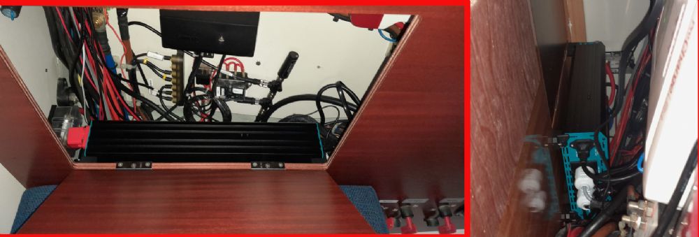 My first worry was where to install the Inverter but got help for this forum ( https://myhanse.com/where-to-fit-a-2000w-inverter_topic13998.html" rel="nofollow - https://myhanse.com/where-to-fit-a-2000w-inverter_topic13998.html ) The requirement was to be able to run a 1000w kettle and other smaller 230v consumers. To be on the safe side the Inverter should be able to provide up-to 2000w. Victron sells a 2000w Smart Inverter 485 X 219 X 125mm for 1000$ / 940 euro. But I chose: Renogy 2000w Inverter with UPS, 442 x 220 x 92mm for 240 euro (280$ for 110 volt version). The Renogy has a smaller case, which was important because I have the 3-cabin Hanse 370, so there is no utility/storage locker. But the inverter must also be very close to the batteries. The Inverter has a UPS function (Uninterruptible Power Supply), but I was uncertain how that could be utilized in my boat. The manual stated that the Shore-Power could pass through the Inverter. Therefore I made quick try-out connecting the Inverter to the batteries and Shore-Power. Beware the first time the Inverter is connected, a huge capacitor is rapidly charged and it made a spark. The Inverter does not need to be turned on, or be connected to the batteries to let Shore-Power pass through to the 2 outlets The Inverter uses 1A (13 watt) when turned on but with no load on the 2 outlets The Inverter uses 0A when turned off. (could not measure any consumption at all) With this knowledge I knew that it would be possible to make a fixed installation with no need to switch plugs/outlets. Also very important that the use of Shore-Power would be handled exactly as before, so the crew would not need education
(update: So the Inverter is only turned on seconds before it is needed, and then turned off after use eg. the water is boiling). When turned off, the Shore-power feeds the galley-outlet and the microwave-outlet as normal) I chose to intercept the galley outlet and the outlet in the closet above the stove( https://www.myhanse.com/220v-connector-behind-shore-power-panel_topic9770_post94486.html#94486" rel="nofollow - https://www.myhanse.com/220v-connector-behind-shore-power-panel_topic9770_post94486.html#94486 ). The galley outlet was marked with 3: galley_outlet.jpg seen from within the sink-cabinet 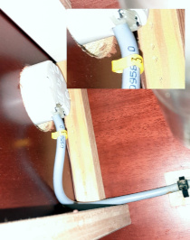 The other end of that cable 3 was found connected to the electric Panel. Electric_panel.jpg. Backside seen from within the cabinet. Very hard place to reach.  When removing the 3 cable it was in a harness with one other 230v cable. I was lucky because the other cable 6. was the one for the microwave outlet! pantry_harness.jpg. Thx. Hanse... 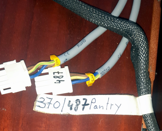 487 is the buildno. For my Hanse 370. Being lucky again, it turned out the harness was quite long. long_harness.jpg 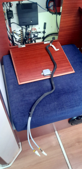 The two wires were cut and Schuko 230v male (CEE 7/4) /female (CEE 7/3) plugs installed schuko.jpg 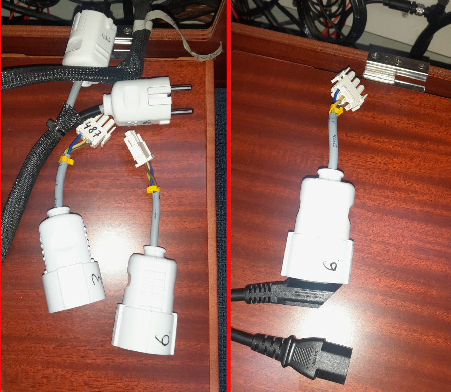 The female plugs were put back into the electric panel and the black wire to the right is going to be the Shore-Power feed to to the Inverter. This way it will be possible to restore the 230v to the galley if the Inverter where to be discarded. Now it was time to look at the 12v DC side. Renogy has a guideline for calculating the Fuse-size: Fuse Recommended = Inverter Watts / Battery Bank Voltage / % Efficiency * 25% safety factor ( https://www.renogy.com/academy/accessories-wiring/Fuses-and-Wire-Gauge" rel="nofollow - https://www.renogy.com/academy/accessories-wiring/Fuses-and-Wire-Gauge ) so 2000W / 13v / 0.90 * 1.25 = 213A I chose a 200A Fuse The cable-length was measured to: 1x20cm red, 1x105cm red, 1x45cm red and 1x85cm black. The inverter black goes straight to the bus-bar. The Inverter red goes to fuse-box, then to the dedicated battery switch and lastly to a positive feed from the 3 Lifepo4 (100AH) batteries. Cable thickness can be calculated with this page https://www.12voltplanet.co.uk/cable-sizing-selection.html" rel="nofollow - https://www.12voltplanet.co.uk/cable-sizing-selection.html The length is 2.55 meters in total (even-through the Inverter sits right next to the batteries
1.7 meters(positive is longer) and 2000w/0.90 = 171 Amps and voltage is always above 13 = 50 mm2 square equals AWG 1/0, is a good choice and voltage-drop is about 1.75%. In Scandinavia there is a Brand called 1852 with Marine Professional tinned cables. I also got fuse-box and a battery-switch that looks like all the others. With a large crimp-tool I could make the cables my-self. The Renogy comes with a remote also. inverterkit.jpg and accessories 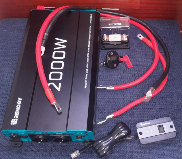 The Battery-switch was installed near all the other switches. But here I made a mistake. The switch requires a 23-24mm hole, and I got a 25 mm drill that I wanted to use. But somehow the 27mm drill found its way to the drilling machine
Battery_switch.jpg 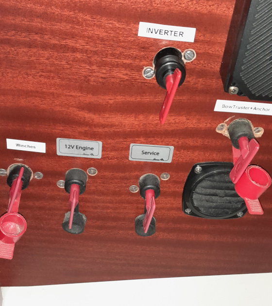 The Fusebox was installed on the wall up against the head, right next to a Ground Bus-bar. fusebox.jpg 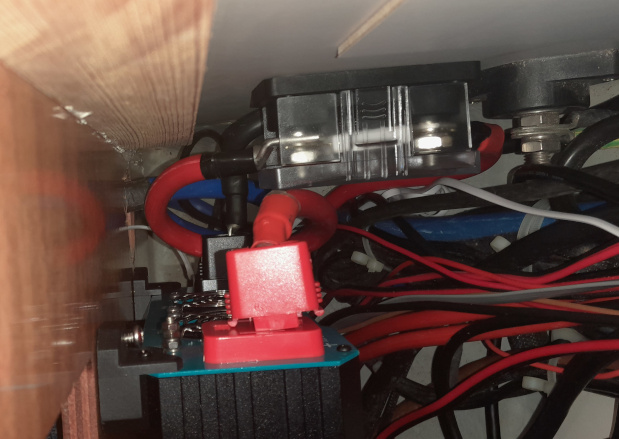 All the thick cables was installed first, then the Inverter was placed into the lower electric cabinet. Beware that the Inverter has a large capacitor and I made a huge spark again when tightening the positive connector and hitting the Inverter Case at the same time. This capacitor must be huge, because when turning on the Inverter for the first time it draws 20 amps. I think it is much more than that but the sampling rate for my shunt is not updating fast enough to show the real instant draw. 1st try. The Inverter was turned on and and the 1L kettle (1000w) was heating the water to boiling point I 6 minutes. The kettle was measured to use 987 watts and the shunt showed it used 86A. The battery Shunt showed that 2.9% of the 300Ah battery capacity were used (approx. 8.7 AH used) The Renogy Inverter is Pure Sine curve but it is built in China, so just to be certain it is a good product I also measured it with a oscilloscope. The Sine curve was rock solid also when turning the 1Kw load off and on. inverter1try.jpg 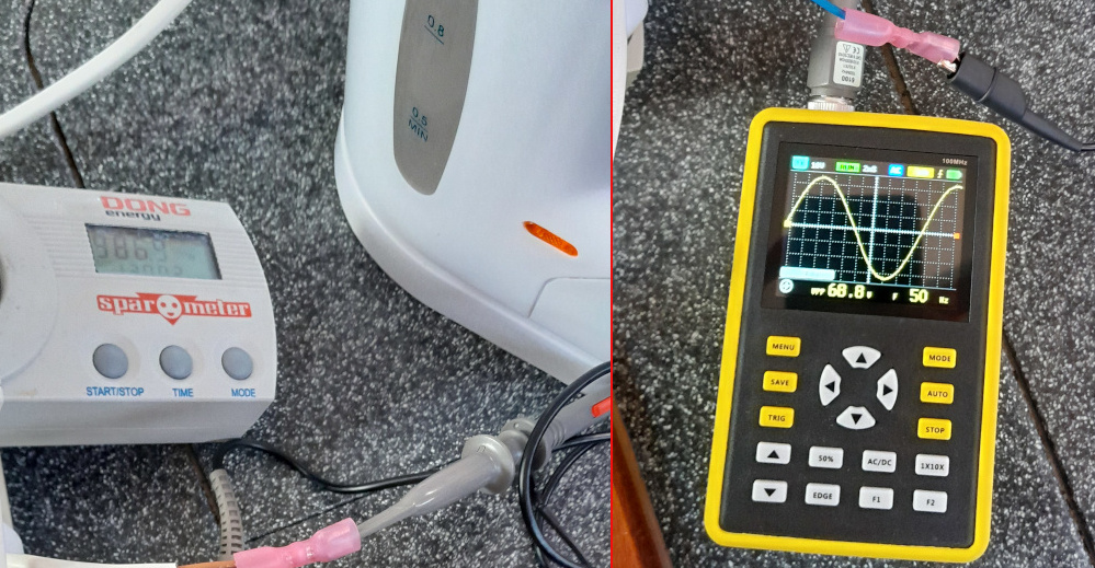 The Renogy states 90% efficent and the cable-loss is approx. 1.75%. So the needed power to use our kettle is 987watt / 0.90% + 1.75% = 1115w. My shunt showed 13.05 volt under load and 86 amps = 1122 watt so the 90% efficiency looks to be correct. 86 amps is a lot so all connections were inspected with a Flir-One thermal camera. Beware the Thermal images look like the cables are red-hot glowing, but they were only 5-7 degrees Celsius above ambient temperature. I will monitor this issue so I am certain no mistakes have been done. Battery switch backside seen from within the cabinet. It shows my crimped terminals are OK. Flir_BatterySwitch.jpg 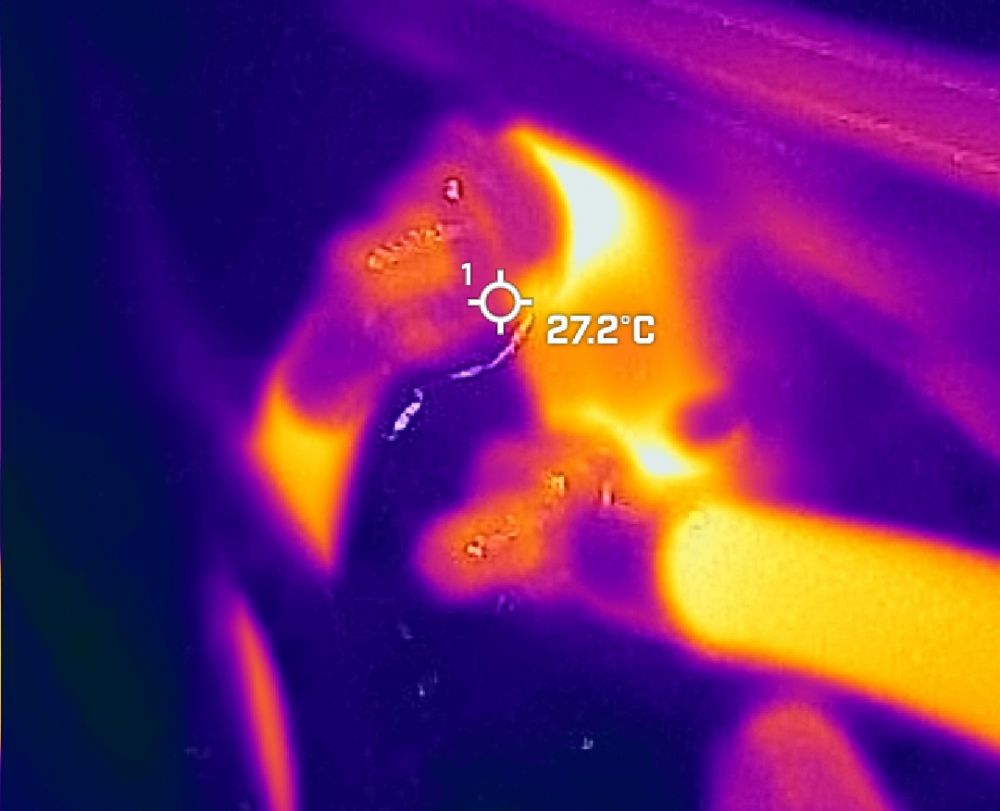 Fuse-box seen from above. The wire has insulating tape wrapped around the terminal because it is located near the negative for the Inverter. And to avoid accidental short_circuit I used tape. But this makes this terminal the hottest part of the entire installation. Flir_Fuse-Box.jpg 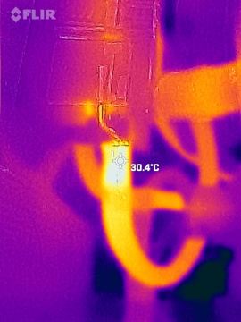 The Renogy inverter has two Fans but they have not yet started spinning. The Renogy had zero to none heat generation with serving 1Kw
Here are some of the more specialized tools I used for installing the Inverter. invertertools.jpg  Was it hard? Not really. But knowledge of high current(12v dc) and mains voltage is needed. I used 10 hours (excluding many hours cleaning up and doing long needed cable management in the electric cabinet). Do to my native language is danish, I also used 4 hours writing this post... I hope this post can inspire others. (BTW. I am in no way sponsored except from alms from my wife :-) /H8jer
------------- Hanse 370#487 30HP 3-cabin |
Replies:
Posted By: Yoda
Date Posted: 10 July 2023 at 23:35
|
Good choice of invertor and nice description of fitting it. Neil
|
Posted By: Jojo
Date Posted: 11 July 2023 at 07:19
|
Well written inspirational instruction how to do Thanks   ------------- 3 Cabin, Hanse 342, Deep draft, Tiller version. |
Posted By: MAJOTE
Date Posted: 17 July 2023 at 12:37
|
Muchas gracias. Muy ilustrativo y descrito correctamente. Próximamente llevaremos a cabo la instalación y nos va a servir mucho la aportación.
|
Posted By: H8jer
Date Posted: 17 July 2023 at 22:22
|
Hi Guys. I am glad that you find the how-to usefull. Tomorrow it is time to install the remote for the Inverter in the electric panel. ------------- Hanse 370#487 30HP 3-cabin |
Posted By: H8jer
Date Posted: 20 July 2023 at 11:41
|
Hi Here is a picture of the installed Inverter Remote. Above the remote is the hour-meter that counts the hours for when the fridge compressor is running. 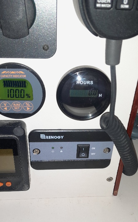  ------------- Hanse 370#487 30HP 3-cabin |
Posted By: H8jer
Date Posted: 13 August 2023 at 08:30
|
Here is an update with a review on how the inverter was used during our holidays. We did not experience any drawbacks but instead the Inverter was a huge success. I will keep it short and list the benefits we saw:
    ------------- Hanse 370#487 30HP 3-cabin |
Posted By: Mark_J1
Date Posted: 20 August 2023 at 10:36
|
H8jer - hi. I have a similar project underway, though in my case it is Round 2 to upgrade the inverter. Looking at your (great!) notes it looks like you take the inverter output to the output side of the Calira 421 panel consumer unit by intercepting cables 3 & 6. If I understand this correctly that means you are not using the installed RCD on the 421 panel. Any reason you didnt connect on the shorepower line input to the 421 panel? Maybe you have a separate RCD in the circuit? Im asking because it really is a lot easier to work on the output circuits. As you say it is a very tight space to work. Mark
------------- Hanse 400e "Grey Goose" Hull #31 |
Posted By: H8jer
Date Posted: 20 August 2023 at 18:52
|
Hi I decided to intercept the 240v wires after the panel to exclude all other outlets than the one at the galley sink and at the microwave in the cabinet above the stove. The water-heater in our boat is a Isotherm 20L Slim which is 750w(have replaced the original). I have tried to be surprised that this was turned on when on shore-power, which indicate, I might forget it again when I turned the water-heater on. This will quickly drain the batteries. So to make it impossible to do this mistake again, - The inverter is an upgrade for the galley alone. The Standard for Schuko plug/outlets allow for up to 3680 watt's with 16 amp fuses and 2400 watt with 10 amp fuses. So the Calira panel could have thicker cables to account for x times outlets. The Renogy has UPS function and it will feed the two outlets with 240v. But the Renogy is powered by the normal 3x0.75mm2 or 3x1mm2 computer-cable type. If I intercept the other side of the distribution-Panel that computer cable would have to feed all outlets at once. (Btw. National regulation in Denmark only allow continuously (more than 2 hours) draw of 6 amps from 240v outlets) Regarding Residual-Current Device (RCD), which we in Denmark call a HFI/HPFI-relay, is for monitoring what current is entering the circuit and what is leaving the circuit. It is also called Ground Fault Circuit Interrupter (GFCI). I believe that GFCI is built into the Renogy Inverter acording to https://www.renogy.com/troubleshooting/Troubleshooting-Guide-Power-Inverters" rel="nofollow - https://www.renogy.com/troubleshooting/Troubleshooting-Guide-Power-Inverters and https://www.renogy.com/troubleshooting/Inverter-and-Inverter-Charger-Troubleshooting-Basics" rel="nofollow - https://www.renogy.com/troubleshooting/Inverter-and-Inverter-Charger-Troubleshooting-Basics Which states: GFCI Problem Symptom: Yellow LED GFCI indicator light is on I have not tested this but I might do this to be certain that there is infact RCD. /H8jer
------------- Hanse 370#487 30HP 3-cabin |
Posted By: Mark_J1
Date Posted: 22 August 2023 at 10:10
|
Understood H8jer. Makes sense. I want the whole AC system served from the inverter so Ive found the Mate-n-lock connectors used with the 421 panel and can now make up an additional wiring harness to intercept shore power, route it to an auto-changeover switch, a separate inverter GFCI/RCD & the inverter itself. Having the connectors makes it plug & play so I dont have to do electrical microsurgery behind the 421 panel! In my use case I want to be able to run the inverter a lot, so I rely on monitoring to warn me of over consumption :) . I usually run the calorifier heating element from a motor speed controller to reduce the input voltage & manage the power consumption down. Often I have it running at just a trickle say 40v to match the available solar input. Effectively a solar dump load solution without swapping to a 12v DC heating element. Mark ------------- Hanse 400e "Grey Goose" Hull #31 |
Posted By: H8jer
Date Posted: 22 August 2023 at 14:01
|
Hi Mark Sound like you are also doing a lot of DIY. Thanks for the headsup about RCD/GFCI. Our usage of the Inverter in more for Day cruising / weekend and holidays use. We are not liveaboards. We have no fixed solar panels installed. Otherwise I think the 3000w Renogy would be more suited for addtional outlets. The huge Victron Charge/Inverter is nice but I have the 3-cabin version and has not a utillity/cargo room for such equipment. ------------- Hanse 370#487 30HP 3-cabin |
Posted By: Mark_J1
Date Posted: 22 August 2023 at 20:33
|
H8jer - agreed re the need for a utility space! The space on the 400 for electronics/electrical gear is tight and awkward to work in. I tried fitting the Victron gear in and its just not viable. Donated it to my sons Narrowboat instead! My 1000W inverter sits hanging under the Nav table & is not visible unless you know its there. Has actually been fine for 3-4 Seasons when used with low power kettle & toaster. With work on solar panels I now actually get 5-20A of charge input consistently on a Sunny day. So I found I had spare power:) Hence the move to a bigger inverter. Im deliberately under rating a 3000W Cotek and have subdivided the forward Nav table seat under locker to fit it in close to the batteries & 421 panel. This can handle the microwave and induction hot plate. So in Summer I think well be gas free unless we are in the rain for a couple of days without turning on the engine. Thats the huge win I was aiming for. Mark ------------- Hanse 400e "Grey Goose" Hull #31 |
Posted By: MAJOTE
Date Posted: 10 December 2024 at 12:50
|
Hola Estoy haciendo el proyecto del inversor y me encuentro con un pequeño problema: El cable nª6 llega hasta detrás de la nevera, y luego asciende por detrás de la cocina, pero lo pierdo entre los paneles traseros puedo ver dónde acaba. ¿Me podéis decir cómo puedo averiguarlo sin tener que realizar un registro o agujero en el panel? Hello, I am doing the inverter project and I am having a small problem: Cable #6 goes to the back of the fridge, and then goes up behind the stove, but I lose it between the back panels and I can't see where it ends. Can you tell me how I can find out without having to make a hole in the panel?
|
Posted By: H8jer
Date Posted: 10 December 2024 at 13:07
|
Hi Sure. In this post I found that the cable was fixed at the backplate for the microwave. This is out of reach, so I just pulled until it got lose. https://www.myhanse.com/220v-connector-behind-shore-power-panel_topic9770_post94486.html#94486" rel="nofollow - https://www.myhanse.com/220v-connector-behind-shore-power-panel_topic9770_post94486.html#94486 ------------- Hanse 370#487 30HP 3-cabin |