Lithium replacement.
Printed From: myHanse.com
Category: Hints & Tips
Forum Name: 415/418
Forum Description: 415/418 Hints, Tips and News
URL: https://www.myhanse.com/forum_posts.asp?TID=14238
Printed Date: 27 March 2026 at 03:41
Software Version: Web Wiz Forums 12.06 - https://www.webwizforums.com
Topic: Lithium replacement.
Posted By: Mike2145
Subject: Lithium replacement.
Date Posted: 06 September 2023 at 14:14
|
Just finished the replacement of the old, and original 9 year old AGMs. They gave good service. I used 305Ah EVE cells,JK-B2A8S20P 200A BMS and Victron DC to DC chargers. If anyone would like the details let me know. ------------- Cant take a joke, don't buy a boat. |
Replies:
Posted By: Mike2145
Date Posted: 06 September 2023 at 14:27

Still a little cable management to be done for the main power cables. Significantly smaller and lighter. ------------- Cant take a joke, don't buy a boat. |
Posted By: SimonGH
Date Posted: 12 September 2023 at 01:11
|
Id love to learn more. Did you change or upgrade the alternator? Why do you have 2 dc-dc chargers? Are they running in parallel? Did you change the ACR or other battery divider? What happens if the BMS shuts off the battery? Do you have a bow thruster? What amperage dc-dc charger are you using? Id love to see your wiring diagram. I have two Lithium banks but havent installed them yet. I feel like Im over thinking it
|
Posted By: Ian Coverdale
Date Posted: 12 September 2023 at 08:02
|
Neat. Assume you've not installed a master isolator switch on LFP +VE as you're using remote on/off switch function of BMS? Do you have an original thruster battery DC-DC converter and is it working okay with slightly higher input voltage? We had Sterling DC-DC thruster battery charger which thought engine was running all time due to slightly higher input voltage as so was a constant drain on LFP battery. Be interested in any niggles once you start using the system. Thanks for sharing :-) ------------- Ian & Andrea SV Gabrielle (H445) Liveaboards - currently Montenegro. www.facebook.com/sailinggabrielle |
Posted By: Mike2145
Date Posted: 13 September 2023 at 13:07
Hi. Ill try and go through each point. I cant do a wiring diagram at the moment but you may not need one. I already had a 120A alternator so didnt need to upgrade. The two DC-DC chargers are paralleled to provide charging up to 60A each can provide 30A, this is about a hard as I would like to push the alternator on a continuous basis. Its more than adequate for the time we run on engine to recharge. Its not the cheapest solution but saves a lot of pain changing the alternator charging regime. The ACR isnt needed as the DC-DC chargers have an engine on detection feature and the default settings seem to work just fine charging the start battery. They are user configurable if needed. The BMS will shut off the battery on low voltage but with lithiums this is at a point where they are almost depleted. However, there is an override for this on the BMS app. For over voltage the BMS will disable charging while allowing discharge so not an issue. The BMS is rated at 200A so I dont anticipate this being an issue as Ive monitored the current draw over several years and only exceeded this a few times momentarily with a stalled windlass. The overcurrent can be configured to trigger after x seconds so these states wont shut down the battery. If it does it resets after x (configurable) seconds in any case. Ive been extremely impressed with the config options. We do have a bow thruster and this has a factory DC - DC charger. It appears to work fine with the lithiums even with the higher steady state voltage and not noticed any significant draw but Ive not actually measured it yet. In essence, after much tracing the wiring diagrams, all that we needed to do was disconnect the feed from the alternator/start battery from the ACR, connect this into the DC-DC chargers and connect the output from them to the main bus bar. At that point the ACR is redundant. I already had a shunt but the BMS has this function as well. Hope this helps. ------------- Cant take a joke, don't buy a boat. |
 SimonGH wrote:
Posted By: Mike2145
Date Posted: 13 September 2023 at 13:20
Hi Youre correct Ive not included a battery isolator as the BMS has this both software and a physical switch. I cant see the make and model of the DC-DC charger for the bow thruster but there hasnt been any parasitic draw that caught my attention but I will do a bit of testing. The system has been running for a week now and, so far, all looks good. The only thing to note, which I was expecting, its that the mains charger, which has no lithium option and is set to AGM, charges fine to 100% at which point the BMS disables the charge as the voltage overshoots momentarily but then the charger goes into float, the BMS re-enables charging, and allow the lithiums to discharge to about 90% and everything settles at that point. We dont get to mains power very often so this is just fine. ------------- Cant take a joke, don't buy a boat. |
Posted By: SimonGH
Date Posted: 21 September 2023 at 20:24
|
I really like this approach and I'm planning on copying it. It seems much more elegant than all the changes I had planned on doing with mods to the alternator, charge divider, etc. My only question - how would I wire up the Victron charger/inverter that I have? My belief is that it's one set of wires to the house battery bus at this point - when the mains are plugged in it acts as a charger, so theoretically you could put that connection on the other side of your DC-DC chargers and they would handle the LiFePO4 charge profile, no? However if you do that, then when you want to run the inverter, the DC-DC chargers won't pull power from the LiFePO4 bank, only the starter battery, correct? If you leave the charger/inverter wired directly to the house battery, then you won't be charging the starter battery, since the DC-DC charger only works in one direction (i think), and you have the issue of an incorrect charge profile as you noted (if you can't reconfigure the charger). What happens if you start the engine while still plugged in? How are you charging the starter battery with shore power in this setup? Do you need another DC-DC charger pointed the other way? Would that work? |
Posted By: Ian Coverdale
Date Posted: 21 September 2023 at 23:37
|
Which inverter/charger do you have Simon? The BMS used here is rated at 200A. This will not be sufficient for larger inverters so depends on how big your inverter is and what other equipment you may wish to use at same time such as windlass, winches, etc. Need to consider your total power requirement. ------------- Ian & Andrea SV Gabrielle (H445) Liveaboards - currently Montenegro. www.facebook.com/sailinggabrielle |
Posted By: SimonGH
Date Posted: 23 September 2023 at 12:41
|
I have the option that came with the boat. Its a Victron multiplus 2000. I actually have two batteries each with their own 200A BMS, so I believe that it should work ok. I noticed while reading the manual that the charger has a second output for a starter battery, so I can probably just use that. The main issue is that it doesnt seem to have a setting for the primary battery chemistry to be LFP, so Ill have to see if I can change the configuration somewhat. The boat is typically on shore power when docked, so I want to ensure the charging is correct for the LFP when plugged in
|
Posted By: Ian Coverdale
Date Posted: 23 September 2023 at 12:53
|
Your Multiplus can be programed for LFP depending on how old it is but you may need firmware update. LFP mode is configured via software, not through DIP switches. Software is free from Victron website but you will need USB/MK3 adaptor. Guide is here https://www.victronenergy.com/media/pg/VictronConnect_Manual/en/firmware-updates.html" rel="nofollow - https://www.victronenergy.com/media/pg/VictronConnect_Manual/en/firmware-updates.html Upgrade is a bit tricky but not difficult. Given knowledge shown here, sure you will have no problems. This document tells you which Multiplus models can be upgraded to latest firmware. https://www.victronenergy.com/upload/documents/manual-VE.Bus-firmware-versions-explained-EN.pdf" rel="nofollow - https://www.victronenergy.com/upload/documents/manual-VE.Bus-firmware-versions-explained-EN.pdf ------------- Ian & Andrea SV Gabrielle (H445) Liveaboards - currently Montenegro. www.facebook.com/sailinggabrielle |
Posted By: Mike2145
Date Posted: 23 September 2023 at 14:53
|
Did a bit of digging. Looks like the bow thruster factory DC-DC is making a small draw with the engine off, about 150mA. Not really a problem. However, with the engine on the Victron DC to DC lithium chargers are supplying a significant current to the bow thruster battery reducing the charge available to the lithiums. 1-10A. Obvious really! I think Ill add the ACR back in and pop the bow thruster DC to DC charger onto the starter battery bus via the ACR as it was from the original factory setup. . Not a big job but finding the cables in the loom could be! I suspect a bit of boat yoga is on the cards.
------------- Cant take a joke, don't buy a boat. |
Posted By: Ian Coverdale
Date Posted: 24 September 2023 at 02:43
|
The problem we had was not the thruster DC-DC charger standby current but the thruster chargers (we have two, bow & stern) periodically switching to boost/absorption mode that depleted the LFP. With higher LFP battery voltage, chargers thought engine was running all the time with power available for charging. Chargers were using up to 30A (x2) in boost mode! We added Victron BP100 on charger inputs controlled by relay in existing BMV712 which monitored engine battery voltage as second input. When engine battery was above 13.5V, BP100 closed energising chargers. I put a ON-OFF-ON rocker switch across the relay contact so chargers can be forced on when shore power connected or forced off when running engine and LFP needed more of a charge. Misbehaving thruster DC-DC chargers was not a problem we anticipated when upgrading to LFP. ------------- Ian & Andrea SV Gabrielle (H445) Liveaboards - currently Montenegro. www.facebook.com/sailinggabrielle |
Posted By: SimonGH
Date Posted: 24 September 2023 at 04:10
|
This is incredibly helpful. I'll see if it can be updated. Thanks!! I also have a DC-DC charger for my bow thruster. It's a Victron 12-24v. I believe the best route would be to connect it to the starter battery side and have both fed by the 2nd charger feed...? Simon
|
Posted By: Mike2145
Date Posted: 30 September 2023 at 10:13
|
If the DC-DC charger has an engine on detection then this, I think, would be fine. The Victron Orion 12-24 has this feature. If not then you may need an ACR in line.
------------- Cant take a joke, don't buy a boat. |
Posted By: Arcadia
Date Posted: 30 September 2023 at 20:50
|
I dont think the Victron DC to DC 12-24 has voltage detection for engine on. ------------- Leon / ARCADIA 2018 Hanse 588 Sag Harbor, NY |
Posted By: Mike2145
Date Posted: 01 October 2023 at 09:13
|
The Victron Orion DC-DC charger range does, its the one I use, but Im not certain about the other variants.
------------- Cant take a joke, don't buy a boat. |
Posted By: Arcadia
Date Posted: 01 October 2023 at 10:25
|
My mistake. The unit installed on my 2018 is a Mastervolt 12-24 which does not have that feature. ------------- Leon / ARCADIA 2018 Hanse 588 Sag Harbor, NY |
Posted By: SimonGH
Date Posted: 02 October 2023 at 19:08
|
Update - I got the Mk3-USB cable, but unfortunately my MultiPlus Compact is an earlier model with the older processor, so I can't update the firmware. So I'm going a similar route to the OP, however I'm adding a charging & inverter contactor so I can connect the Charger/Inverter to the "feed" side of the DC-DC chargers when in charger mode, and then switch over to the LiFePo4 "battery side" with larger conductors when in "inverter" mode. That way the new DC-DC chargers can handle the LiFePo4 charging profiles, but when I need the high current draw for the inverter, things are connected directly through to the battery... I'll post a wiring schematic for comments. Would love people to poke holes thanks Simon
|
Posted By: SimonGH
Date Posted: 02 October 2023 at 19:18

|
Posted By: Arcadia
Date Posted: 02 October 2023 at 21:33
|
Just curious. Why the ground relay on the inverter ? ------------- Leon / ARCADIA 2018 Hanse 588 Sag Harbor, NY |
Posted By: Arcadia
Date Posted: 02 October 2023 at 21:43
|
Also, you should have a high current cable from the alternator to the inverter for large AC loads while the engine is on. ------------- Leon / ARCADIA 2018 Hanse 588 Sag Harbor, NY |
Posted By: SimonGH
Date Posted: 03 October 2023 at 01:12
|
Ah, good catch. As for the ground relay
. I spent the extra $ on isolated dc-dc chargers because the BMS systems on my batteries are on the negative side, so I figured it was good to keep things isolated. But when I started sketching in the inverter I realized that if I didnt put that relay in I would be bridging the isolation of the dc-dc chargers, so I figured Id need it to keep it separate. Overkill? Nothing is installed yet but I do have all the parts
|
Posted By: Mike2145
Date Posted: 03 October 2023 at 10:10
|
Its a shame the hardware cant be updated on the charger. The only things I noticed were that K1 may actually be redundant. Connecting Vin and Vout on the DC-DC charges wouldn't be a problem, I think. Perhaps someone with more knowledge of these could help? Is K4 needed? The negative side may all be common already? It was on my 415. The feed from the service battery is probably already fused, but not shown, so additional fuse on the mains charger to DC-DC charger may be required. There is the possibility that the engine could be started while on shore power so there could be a point at which the start battery is directly connected to the service battery. You could run the negative to the ACR through a NC relay operated via SW1 for belt and braces. This is quite a lot of heavy duty cabling and the relay(s) will need to be pretty beefy to cope with the current for the inverter not to mention the additional fuse(s). So a reasonable amount of work to connect the mains charger to the service battery via the DC-DC charger. From my experience, so far the AGM, setting on the mains charger settles to about 92% charge (the BMS takes care of any anomalies during initial bulk and absorption phase) for the Lithium so by keeping the cable changes to a minimum by leaving the charger directly connected to the service battery, its pretty near factory set up, I have not had an issue with this. The short period of motoring I have when leaving shore power usually brings the service battery back to near 100%. Would it be worth keeping it simple first and see if the additional work is needed? You can always make the changes later? Just a thought?
------------- Cant take a joke, don't buy a boat. |
Posted By: Mike2145
Date Posted: 03 October 2023 at 10:15
|
Our posts crossed! I see now you used isolated DC-DC chargers. Ignore my comment I didn't catch that.
------------- Cant take a joke, don't buy a boat. |
Posted By: Mike2145
Date Posted: 03 October 2023 at 10:29
|
That is a good point, I'm not sure if the alternator/start battery would be happy about the possible load let alone the cabling/fuses. It may be wise to add another relay to prevent this from happening, triggered from SW1 as mentioned in my earlier post, the belt and braces approach. Not adding the relays and keeping the charger directly connected to the service battery avoids this issue. Another factor to complicate the decision making process!
------------- Cant take a joke, don't buy a boat. |
Posted By: SimonGH
Date Posted: 03 October 2023 at 11:38
|
With regards to the inverter running off the alternator, isnt that how it is currently connected? I intend on reusing most of the existing wire, I believe the cable running from the engine bay to the batteries through the ACR is pretty beefy. I wonder now if I need K1. If the engine is off and the charger is in inverter mode, then nothing is happening on the Vin on the dc-dc chargers anyway. I am assuming that they dont run backwards (I.e. Vout feeds Vin)
So I could simply move that to disconnect the inverter from the alternator instead
? |
Posted By: Mike2145
Date Posted: 03 October 2023 at 12:07
|
The inverter will be connected to the alternator directly currently but also to the service batteries. The service batteries will supply the required current when the alternator reaches its maximum. However, the new set-up removes the service battery leaving only the start battery and alternator to take the load. I doubt the cabling/fusing is capable of supporting this and its probably not something I would like to do in any case given the loads involved and the strain on the alternator. Don't forget that at 2KW the draw at 12v would be over 160A. I would make sure that in the proposed configuration the inverter is prevented from drawing exclusively from the alternator and start battery. Because of the setup you effectively prevent the use of the inverter with engine on. It would be possible to add another set of heavy duty relays for this but its getting complex. Something else to consider is that you may forget to switch off SW1 with the current setup, as I mentioned , connect the service batteries direct to the alternator but if this is locked out with an additional relay for safety, forgetting to switch off prevents the service batteries from charging. Not a big problem but another thing to consider. Anything that needs manual intervention will always fail at some point. (Don't ask me how I know this!) It will be a lot simpler, and almost cheaper with labour and components, to replace the inverter charger with one that supports Lithium if using the AGM setting isn't sufficient to meet your needs rather than a lot of additional complexity. I would still be tempted to keep the current charger directly connected and see how you get on. You might even be able to 'tinker' with the AGM profile a little in the software to make it a little more compatible? Would be really interested to see what you decide and how you get on as I'm considering adding a bigger inverter to replace the factory 350W unit. So inverter or new charger inverter will be my next decision.
------------- Cant take a joke, don't buy a boat. |
Posted By: SimonGH
Date Posted: 03 October 2023 at 14:30
|
Here's the original wiring currently in the boat. The inverter/charger is already connected to the alternator & start battery through the ACR. So not sure what changes when I put the LiFePo4 batteries in with the chargers. When in "inverter" mode, the setup is effectively the same, because the DC-DC chargers are disconnected and the large contactors connect the inverter directly through the batteries. The Alternator/Start battery/ACR connections remain the same, and it currently works correctly (this was the original layout from HANSE... Am I missing something? 
|
Posted By: SimonGH
Date Posted: 03 October 2023 at 14:38
|
This is with the Inverter "ON". The stuff in the grey box is inop, and the big contactors just reconnect the batteries to the inverter. I'm a mechanical engineer, so this is somewhat mysterious to me... but does this make sense? The only difference here is that the 12/24 DC-DC charger is also disconnected in Inverter mode, so there is a risk that if I leave it on then it won't get charged. I have it shown here as a discreet switch. I'm looking to see if there is a way i can trigger it from the same control panel as the inverter/charger, so it works automatically when the VEBus panel is switched to inverter. I'll also add that my use case is different - I spend a lot of time at Marinas plugged in, so that's why i wanted to make sure when on shore power the LiFePo4 batteries were being charged correctly... 
|
Posted By: Mike2145
Date Posted: 03 October 2023 at 15:49
|
I think that this is what you're trying to achieve. This ensures that the invertor can't draw from the start/ Alternator side only, it also prevents the start/alternator side being directly connected to the Lithium Service battery. You will need to use the dedicated start battery output from the charger rather than common up the main output for both service (via DC-DC) and start. K5 just needs to be a low power relay. A standard automotive one would be fine as its not handling any significant current. It will effectively switch off the ACR (K3) when SW1 is on isolating the inverter and lithium's from the start and charger side when the engine is running. 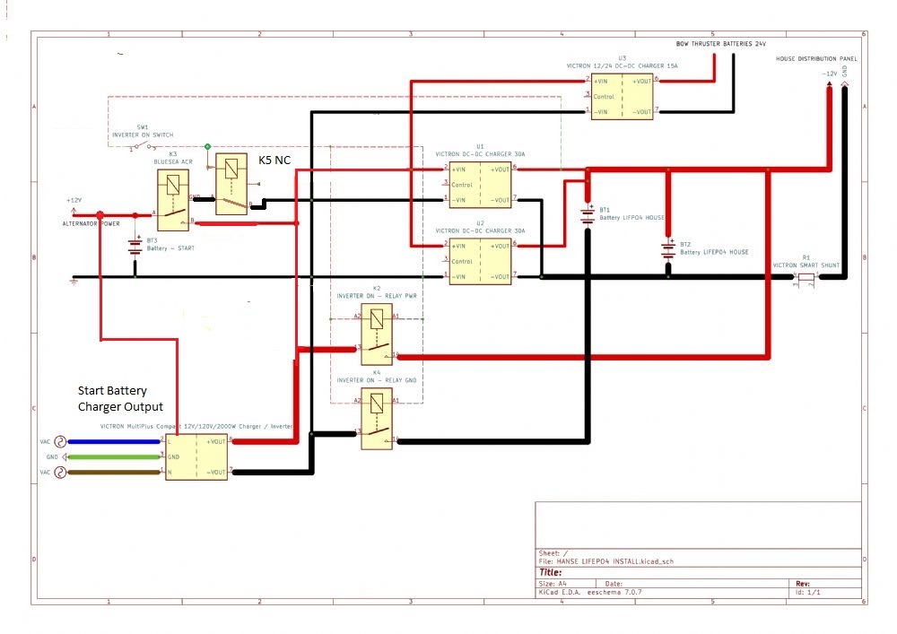 Is the switch SW1 part of the charger/inverter? If not then there is still a possibility of the inverter drawing from only start and alternator if you forget to switch it on prior to using any significant draw on the inverter. It would probably be OK as I suspect the inverter will just shut off with low input voltage but its not ideal. Is the switch SW1 part of the charger/inverter? If not then there is still a possibility of the inverter drawing from only start and alternator if you forget to switch it on prior to using any significant draw on the inverter. It would probably be OK as I suspect the inverter will just shut off with low input voltage but its not ideal. ------------- Cant take a joke, don't buy a boat. |
Posted By: Mike2145
Date Posted: 03 October 2023 at 16:22
|
You could try this to start? Minimal change and if you're not happy with the AGM charge profile on the Lithium's and need to change, none of these changes need to be undone. Gives you the option for adding the additional relays or a new inverter/charger at a later date. Using the 'engine on' feature you can eliminate the need for the ACR and this also charges the thruster battery on shore power as well as engine. 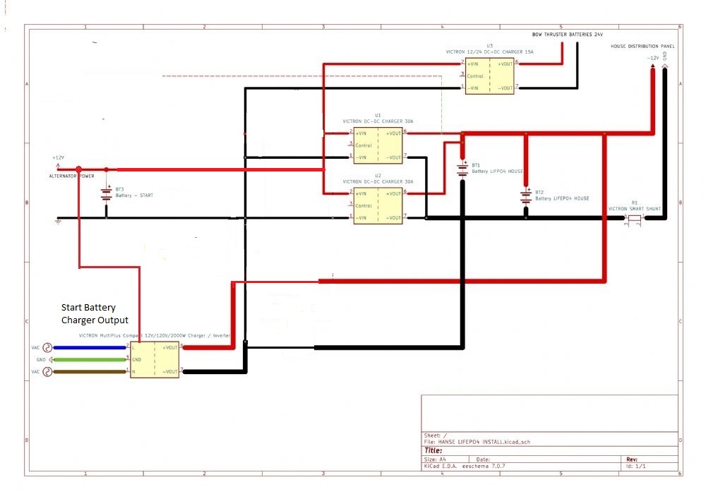 ------------- Cant take a joke, don't buy a boat. |
Posted By: SimonGH
Date Posted: 04 October 2023 at 19:41
|
Yes, much simpler. I've got to delve into the specific charging behavior of the MultiPlus Compact and what settings are adjustable. I've also got to get a bit smarter on what is "good enough" for LiFePo4. There's a lot of misunderstanding around "float" charging, and ultimately as far as i've learned it's literally impossible to "float" LiFePo4 batteries because that's not how their chemistry works. So it's more about what the bulk & absorption voltages are, and what the charger does when it hits those thresholds. We're coming into the winter months so I've got plenty of time to figure it out properly. I will say that my original plan was to use the Nordkyn device to control the alternator output, and prior to that I bought a bunch of Balmar stuff, so at this point its less about the cost and more about doing it properly. I also realize I was way more focused on the alternator output side (which is solved by the DC-DC chargers), and didn't think about the inverter/charger, which is proving to be more important! I'm not about to drop +$1200 on a new inverter/charger because I'm too lazy to learn however...! I think either way will work - but simplicity would be better. more to come!
|
Posted By: Ian Coverdale
Date Posted: 05 October 2023 at 14:20
|
Which firmware version of the Multiplus do you have, Simon? Going 'lithium' is rarely straightforward and frequently marketed term 'drop-in replacement' is laughable. Those boasting of no issues are either ignorant of the pitfalls or glossing over them! ------------- Ian & Andrea SV Gabrielle (H445) Liveaboards - currently Montenegro. www.facebook.com/sailinggabrielle |
Posted By: SimonGH
Date Posted: 05 October 2023 at 16:04
|
Hard to say - I know the processor sticker starts with a "20" I reached out to Victron, and apparently I can "probably" configure things with VEConfigure and the Mk3-USB dongle. It won't talk to the newer VictronConnect software. Of course that means I need to figure out a windows PC / dual boot, as I'm a Mac person and VEConfigure doesn't work on anything but windows. Nothing is easy! So I reordered the Mk3-USB dongle (I had returned it, love Amazon), and will try again with a PC and the VEConfigure software. The Victron guys said that the MultiPlus will be generally fine, there is an "equalization" feature that needs to be deactivated and the absorption voltage may need adjusting. I'm not too worried about getting lots of telemetry out of it, I figured with the smart shunt, dual BMS, and all 3 DC-DC chargers (the 2 12/12 and the one 12/24) giving me information, I have a pretty good insight into what's going on... more to come!
|
Posted By: Ian Coverdale
Date Posted: 05 October 2023 at 16:31
|
Understood. Also 100% Mac here but have one dual boot Mac for odd bit of software such as VE config. Originally had old 2013 Multiplus 12/1600/70 which with latest firmware for that model was fine for LFP ... had LFP mode in config software. You must have very very old Multiplus if it cannot be updated? Even with Mac dual-boot running VE config, we still needed MK3-USB dongle. Assume that hasn't changed. That size is your alternator BTW. ------------- Ian & Andrea SV Gabrielle (H445) Liveaboards - currently Montenegro. www.facebook.com/sailinggabrielle |
Posted By: SimonGH
Date Posted: 05 October 2023 at 20:13
|
The boat is a 2014, and i'm almost certain it's the factory install... The "20" isn't compatible with VictronConnect so that's where I stopped. So once I get that USB dongle and connect to it to my dual boot mac (which i just sorted out) with VEConfigure, I'll see if I can use VEFlash to update the firmware (or at least see what settings are in there). Who knows, it may already have an LFP mode... Will know more this weekend. At least I'm learning a lot. The OP gave me a novel path that I think ultimately is going to work out really well. |
Posted By: Mike2145
Date Posted: 06 October 2023 at 09:58
|
Edit, I made an error here, depending on the type of DC-DC charger for the bow thruster. If the charger doesn't have an engine on function, I think you said it didn't, then just run the supply for it via an ACR. As the existing one is now redundant then you can use this. A bit of an overkill but easy to do This is, in fact what I have now done. 
------------- Cant take a joke, don't buy a boat. |
Posted By: SimonGH
Date Posted: 11 July 2025 at 11:01
|
So thread bump I never got around to changing this, because ultimately things were working and I didn't want to spend the time on the boat doing it - rather be sailing! But now I'm motivated, as we are anchoring more, and I've determined if I do it properly I can actually run the AC unit for a limited time from the inverter with the right battery setup & charging capacity. I'm coupling this with a generator & solar panels. I am going to go with the much simpler setup and see if I can either live with the current charger profile for the lithium (through the BMS), or finally figure out if i can update the firmware. So based on some further research - the Orion 12/24 charger for the bow thruster has an "engine on" capability, so I don't need the ACR as far as I can tell. So my biggest question is where do I connect the input from the MPPT solar chargers - was assuming they would go on the battery side of the DC-DC chargers (i.e. direct to the lithium cells)? or do I put them on the alternator side, so that they would theoretically feed the starter battery and bow thruster as well? Is it just preference vs one would work vs the other not? Regarding generators, my plan is to use a propane powered portable unit that just sits on the swim platform when at anchor, and a short "shore power" cord plugs into it directly. So as far as the boat is concerned, it's just connected to shore power... I am actually going to do this soon, as we have a long trip coming up in August and I would really like to use my AC while at anchor... |
Posted By: SimonGH
Date Posted: 07 September 2025 at 16:08
Ok, I did this mod completely. It was extensive & pretty complex, primarily because I decided to engineer and build my own batteries to perfectly fit the space for maximum capacity. If anyone is interested in the design I can post a more detailed description with models etc.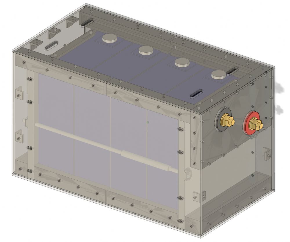 So I was able to fit 3x 340Ah LiFePo4 batteries in the space, with 2x 12v DC-DC 30Amp chargers and a victron smartshunt. It was tight (see pic) but ultimately all fit. The only thing not shown is the two large 2020 aluminum rails that I put across the tops to hold everything securely. What you can't see is the two massive bus bars i used to connect the battery terminals (they are on the side of the battery near the chargers), with one bar above the other (I staggered the terminals vertically so I could do this). I utilized the separate charging feed for the starter battery from the Victron inverter/charger, and I am happy to report I can pull +150Amp to run the front AC on battery for about 6 hrs. (I installed a soft starter on both AC units, that's another story). My only issue is that the older Victron MultiPlus compact 12/80/2000 doesn't reliably charge the batteries past about 70%. I tried everything, but the processor is the old version and i can't update the firmware to have specific lithium charge profiles. So when it hits the set voltage, it switches to float and doesn't charge beyond that (I can see each battery BMS via an app & bluetooth, so I can see the charge/discharge for each battery). For now, this is ok, since there is so much capacity that even 70% full batteries are fine for most uses, just not running the AC for long periods (not an issue since it really hasn't been very warm at night here). But eventually I would like this to work, but I'm really dreading having to drop another $1500 on a new inverter/charger. I'm wondering if I can add an additional AC-DC battery charger (with LiFePo4 profiles) in the system (even if it's relatively low amperage) just to slowly get the batteries to 80-90% charged... thoughts?  |
Posted By: Ian Coverdale
Date Posted: 08 September 2025 at 08:44
|
Yes, I had to ditch my older 12/800 Multiplus when upgrading to LFP. For most BMS systems, you really need a 100% charge from time-to-time for the cell balancing to work and to reset the SOC calculation which becomes inaccurate over time. You could look to add a small separate LFP compatible mains charger such as Victron Blue Smart 12/20 charger which can be wired in parallel with the Multiplus and left on all the time when connected to shorepower? Just one other comment ... many DIY systems miss a master 'emergency' battery isolator switch ... I cannot see one in your photo. If you have an electrical fire onboard, being able to kill the battery supply immediately may save your boat. ------------- Ian & Andrea SV Gabrielle (H445) Liveaboards - currently Montenegro. www.facebook.com/sailinggabrielle |
Posted By: SimonGH
Date Posted: 09 September 2025 at 11:31
|
Hi Ian - I'm going to try this: https://www.victronenergy.com/chargers/blue-smart-ip67-charger-waterproof" rel="nofollow - https://www.victronenergy.com/chargers/blue-smart-ip67-charger-waterproof 12/25 hopefully is a good way to go, and a lot less expensive than a new inverter/charger. Agree, getting to 100 occasionally is important. Right now the only way that happens is if I motor for an extended period - then the twin 12-12 DCs eventually get you there, but at ~1000Ah it can take awhile at 60A... (5 hrs to go from 70 -> 100% SOC) Excellent comment on the disconnect - I do have an isolator switch - the main positive goes through it before it goes to the distribution bus bar - you just can't see it in the photo as it's on the side where the breaker panel is (in the photo it would be beneath the USB charger that's plugged into the AC outlet in the upper right of the image). |