Fuel Tank Sensor Replacement
Printed From: myHanse.com
Category: General
Forum Name: Chit Chat
Forum Description: Talk about anything to do with your boat
URL: https://www.myhanse.com/forum_posts.asp?TID=9181
Printed Date: 27 March 2026 at 03:51
Software Version: Web Wiz Forums 12.06 - https://www.webwizforums.com
Topic: Fuel Tank Sensor Replacement
Posted By: Fendant
Subject: Fuel Tank Sensor Replacement
Date Posted: 18 August 2015 at 14:47
I am posting this under Chit Chat, as it obviously concerns all models. Hanse uses a mechanical automotive sensor, which often gets stuck and provides erroneous readings. Within 10 minutes this can be corrected by a drop in interchangeable capacitive Phlippi sensor. You to order the following parts ( example is for the 160 ltr tank on Hanse 345 ): 1) Tanksensor TGT 250 P/N 6 6011 7081 ( Other models check the tank height ¨) 2) Adapterflange P/N 6 6010 9010
Remove the old sensor, place new seal over the SAE hole pattern and screw adapter flange into existing threads ( don't forget the little O-ring seals on the screws ! ) Screw new sensor into adapter and connect into existing wire  ------------- Frank |
Replies:
Posted By: 415 Singapore
Date Posted: 05 October 2015 at 09:32
Hi thanks for this, we too were getting fed up with crazy readings on the fuel sensor, so have changed the fuel sensor as you described above, having first checked the depth of the tank  However I decided to go one stage further and replace the water tank sensors at the same time, so measured the depth of those too! However not being an electrician It didn't occur to me that they original water tank sensors work differently and have 5 wires instead of the two on the Philippi TGT sensors, is there a work around to this or do I have get new new sensors? Any thought would as ever be much appreciated All the best Paul - Night Train  ------------- Paul - Night Train - 415 #136 |
Posted By: Fendant
Date Posted: 06 October 2015 at 06:01
|
Hi Paul, the TGT sensor is resistance based. I did the same. You only need two wires. I used the two outer wires from existing cable from the tank to the switch panel. You can either cut the plug off or use a standard electronics male connector to get the two wires connected to the display instrument. Does the thread of the TGT sensor fit into the existing crappy 5 wire Osculati flange ? ------------- Frank |
Posted By: 415 Singapore
Date Posted: 06 October 2015 at 06:59
|
Hi Frank Thanks for the reply, do you have the Wuerth panel? I have been told that if you bridge pin 1 and pin 5 of the 5 pin connector at the panel it will work. I am still not sure which of the five wires I should use to connect the new sensor and have asked for further clarification. Unfortunately the TGT sensor thread is far larger than the existing flange, but I am reasonably confident I can resolve that bit, it is the electrics that baffle me! ------------- Paul - Night Train - 415 #136 |
Posted By: Fendant
Date Posted: 08 October 2015 at 07:44
|
Hi Paul, I used the split flange with the 1 1/4" thread to mount the sensor. However I did not connect it to the Würth Panel. I used the Phlippi TCM tank Monitor instead. As this is a pure resistance measurement i used wire 1 and wire 5. I am not sure if this works with the Würth Panel. At least you need to c.hange the Input o 0 - 180 Ohm. Just try it out, ist digital ------------- Frank |
Posted By: spam
Date Posted: 27 April 2021 at 02:02
|
Hi All: I am trying to mount a decent water sensor in the water tank. Managed to pull the crappy 5 wire one out after some persuasion and found the port is really tiny. Looks like the hole is about an inch diameter. How did you go about installing your sensors? What sensor did you use. The standard KUS/Wema ones I am aware of are around 1.4" and the flange is around 1.5". Did you just drill another whole in the tank? Drill out the flange that is there? Or can it somehow be made larger? Harold Ventus, Boston Hanse 415/#314
|
Posted By: Merinalle
Date Posted: 27 April 2021 at 06:19
|
I left the old system as it was. Just installed a new sensor to another place, and a new gauge and an ON/OFF switch next to the panel. ------------- 320#166 |
Posted By: Fendant
Date Posted: 27 April 2021 at 10:49
Same here!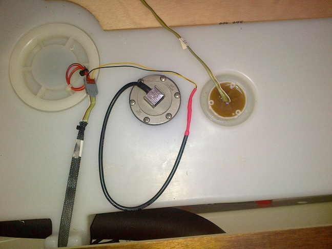 ------------- Frank |
Posted By: richz
Date Posted: 27 April 2021 at 20:13

I used the same hole; obviously you need to widen it to adjust it for the flange size. ------------- |
Posted By: spam
Date Posted: 27 April 2021 at 21:30
| Great, thanks for the feedback. For those that installed a new flange, did you bed it? If so what did you use sikaflex or something else? Or do you just rely to the rubber seal? Did you bolt through and have nuts on the inside (I noticed the inspection hatch is open) or screw in the tank? |
Posted By: pdc78
Date Posted: 28 April 2021 at 06:10
|
I cut a fresh hole and used a Wema threaded flange on the underside. No sealant used, just the rubber washer which came with the sender, then carefully tightened the screws using opposite sequences, then again and again. So far no leakage (fingers crossed!) Regards, Paul ------------- H345 #269 |
Posted By: Fendant
Date Posted: 28 April 2021 at 17:55
|
Correct, I used nuts and washers from the inside, its an easy fit through the inspection hole and a rubber seal on the outside. So far ( 6 years ) its watertight ------------- Frank |
Posted By: richz
Date Posted: 28 April 2021 at 19:42
|
same here: no Sikaflex the rubber seal is good enough. ------------- |
Posted By: Amygdala
Date Posted: 24 July 2025 at 14:39
|
Hi Fendant, I notice in your post that you had the same problem as I probably have in my 385/2014. The tank installation seems equal at least for the sensor in the polypropylene tank. What I am asking is what happens if I unscrew the five fastening screws? Will nuts and washers then disappear to the bottom of the tank or are the screws threaded into integrated threads in the polypropylene?
|
Posted By: Fendant
Date Posted: 26 July 2025 at 13:19
|
Hello Erik, I assume that you mean the black HDPE fuel tank. This one has a molded in flange with threaded inserts. I have attached a photo for your convenience, ------------- Frank |
Posted By: Amygdala
Date Posted: 06 August 2025 at 22:17
|
Hi Frank, Thank you so much for your answer and assurance about the threaded inserts. Tonight I opened the tank and luckily diesel consumption was enough for the level to just be in line with the gauge opening. If it had been above, I would have had a terrible mess to clean up. My gauge seems however to be working just fine, bearing in mind that there is a considerable volume «above» the gauge flange to be consumed before a change in the reading may be possible.
|
Posted By: Fendant
Date Posted: 07 August 2025 at 17:31
|
Erik, I never fill the diesel tank above 90%. My 1st fill up at 100% resulted in diesel smell for weeks, since then at 90% no problem Happy Sailing ------------- Frank |