|
| |
| Welcome to myHanse.com the forum for Hanse Yachts owners throughout the world. | |
Broken Mast Stand |
Post Reply 
|
| Author | |
on y va 
Sub Lieutenant 
Joined: 28 April 2021 Location: Brabant Status: Offline Points: 6 |
 Post Options Post Options
") Thanks(0) Thanks(0)
 Quote Reply Quote Reply
 Topic: Broken Mast Stand Topic: Broken Mast StandPosted: 29 September 2025 at 16:29 |
|
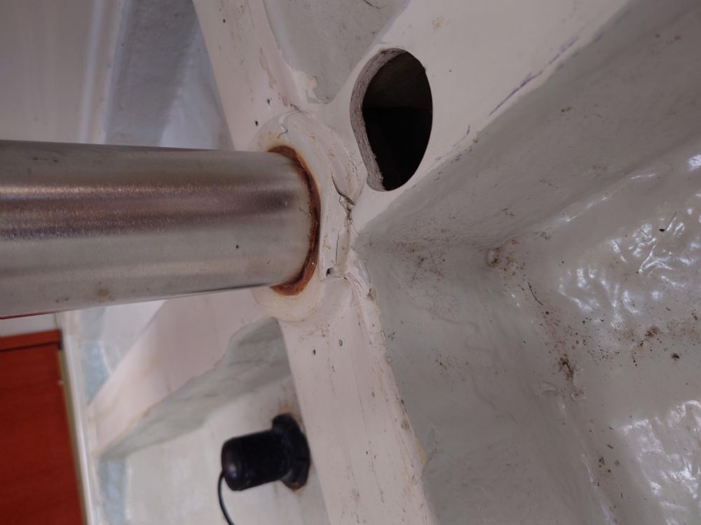
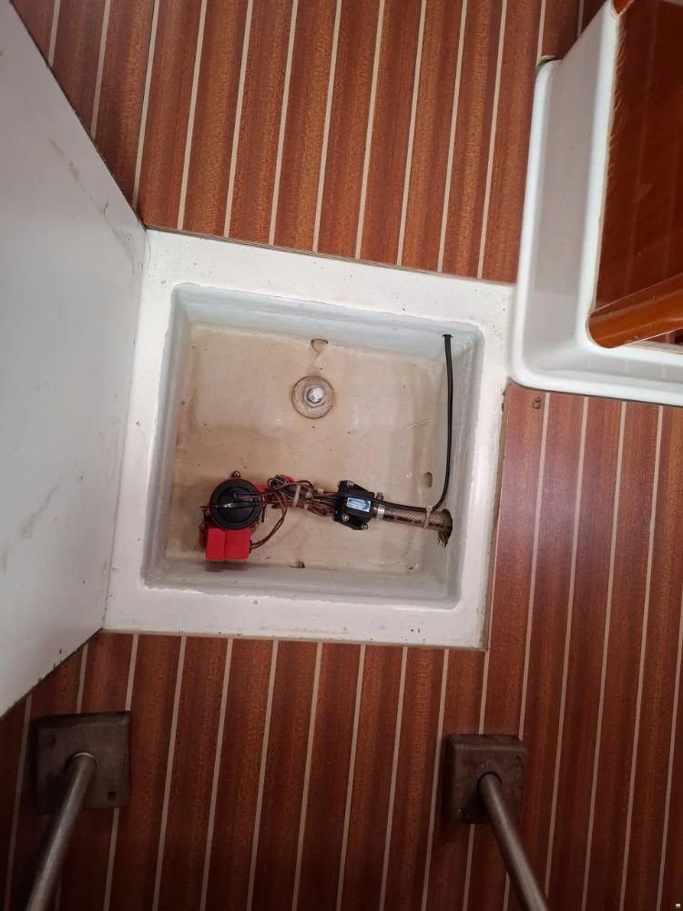
Hello, I was wondering if someone have more technical information about my ship? Between the deck and the keel is a powl (the mast stand). In the bottom, cracks are appearing in the fiberglass.
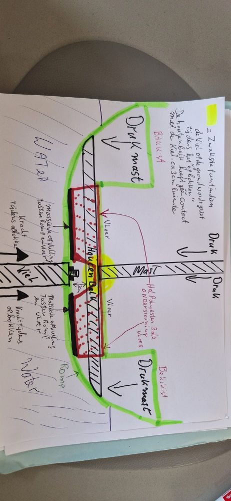
For now, my impression is that the damage is limited to the fiberglass of the stringers. Inside of the damaged Springer is a wooden Beam. Approximately 5 times 8 centimeter, that stretches to both sides of the schip. The beam seems fully in tact after checking it with a endoscopy camera and is bone dry. Im surprised to see that the mast support stops on top of this beam and not on the keel. We are able to fit our hand between the beam and the haul / keel. We re really surprised by this construction. To my (and my technical harbor friends) knowledge a mast support should always rest/ put compression from the mast on the keel. Could someone tell me if our interpretation of the constitution is correct? and what the filosofie behind this is? I put also 2 drawings in the attachment, are they correct? Is this on all the Hanse 311 and 312? Also I have
carefully inspected the deck around the mast foot and could not find any cracks
or visible deformation. kind regards, Nico
|
|
 |
|
|
Jesper2603
Sub Lieutenant
Joined: 27 August 2025 Location: Kerteminde Status: Offline Points: 8 |
Post Options
Thanks(1)
Quote Reply
Posted: 05 October 2025 at 16:48 |
|
Hello, I have the exact same problem/question. I have bought the 311 two months ago. Could this deformation come from a grounding? Is there a need for a repair? Brgds Jesper
|
|
|
|
|
Forth2
Lieutenant Commander 

Joined: 23 October 2016 Location: Finland Status: Offline Points: 77 |
Post Options
Thanks(1)
Quote Reply
Posted: 20 October 2025 at 21:27 |
|
I think the rationale of the design is to spread the load to larger area of
the bottom. The mast force cannot be directed straight down because all of the keel is located aft of the mast support. Only the tip of the keel sole extension is located straight under the mast support. The beam under the mast support flexes a little bit when it is loaded and therefore the gelcoat cracks. As long as the beam GRP does not fail I don't think there is a need to repair it. |
|
|
|
|
FrankS
Lieutenant 

Joined: 06 March 2016 Location: The Netherlands Status: Offline Points: 42 |
Post Options
Thanks(1)
Quote Reply
Posted: 21 October 2025 at 16:59 |
|
on your photos it seems that in the past someone has applied an extra (grey) layer of polyester.Do you know the reason for that ? Is it possible that there has been a grounding resulting in more cracks in that area?
|
|
|
Hanse 345 2016 "STYX"
|
|
|
|
|
Arcadia
Admiral 

Joined: 27 November 2017 Location: Sag Harbor, USA Status: Offline Points: 1112 |
Post Options
Thanks(1)
Quote Reply
Posted: 21 October 2025 at 18:40 |
|
The reason for this design is that the hull is supporting the keel. Not the other way around. The keel is hanging from the hull. If the mast load pushes at the single point at the keel it will only increase the stress at that point. Instead, the wooden beam spreads the load to the rest of the hull and avoids putting more stress at the keel. The best place to transfer the load is as close to the shrouds as possible. That is where the downward forces start.
Edited by Arcadia - 21 October 2025 at 21:26 |
|
|
Leon / ARCADIA
2018 Hanse 588 Sag Harbor, NY |
|
|
|
|
on y va
Sub Lieutenant
Joined: 28 April 2021 Location: Brabant Status: Offline Points: 6 |
Post Options
Thanks(0)
Quote Reply
Posted: 21 December 2025 at 18:46 |
|
Thank you
all for the responses. November was a busy month but of course the 311 was also
on my mind. Unfortunately Dutch wintertime is too cold to do polyester work
outside. Therefor I have a lot of time to research. @Jesper, I
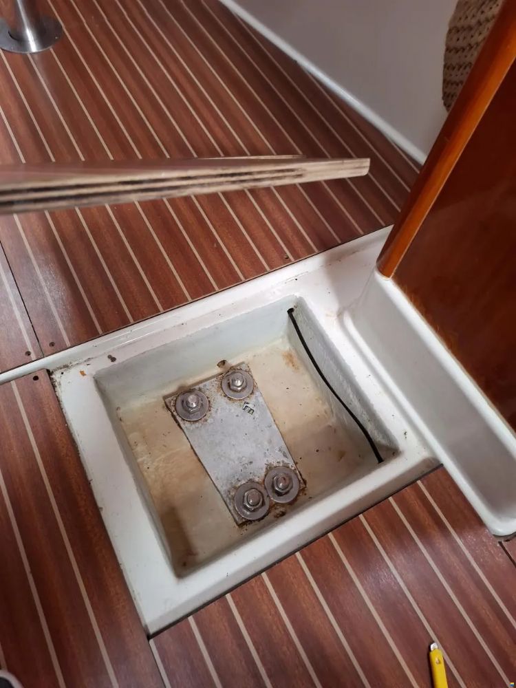
can imagine grounding(s) can cause this problem. In my first poste you see the
hole nest to the keel bolt (on the up side down picture, Im not that good in
uploading on the form yet). In my opinion this is the weakest point in the
construction. This was confirmed by my polyester shop. I would advise everyone
where this part isnt deformed yet to reinforce it with epoxy/polyester.
Preventing this seems the best solution to me. Unfortunately to latte for me.
Can you poste pictures of your keel situation? Towards
your second question, Im planning to repair it. Im sailing a lot on the
Grevelingen lake in the Netherlands, it can be shallow so sometimes soft
groundings can happen. @Forth and
Arcadia, I agree to your philosophies of the ships construction design. -
The
keel is hanging from the hull, -
The
GRP beam (stringer) gives strength to the hull -
The
wooden beam transfers the pressure of the mast towards the shrouds. So the
pressure of the mast is not on the keel. Ive been
to a boatyard and they expect that the wooden beam is rotten and needs to be
replaced. The complete GRP cross around the mast stand should be renewed
including de wooden beam that supports the mast. Fixing cost: unrealistic for a
young sailor like me. Since the wooden beam is bone dry I dont believe
in this rotten beam story. More about that in my next poste.
|
|
|
|
|
on y va
Sub Lieutenant
Joined: 28 April 2021 Location: Brabant Status: Offline Points: 6 |
Post Options
Thanks(0)
Quote Reply
Posted: 21 December 2025 at 18:52 |
|
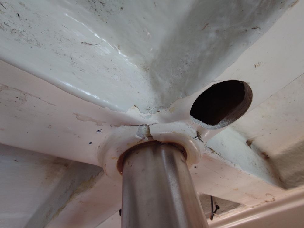
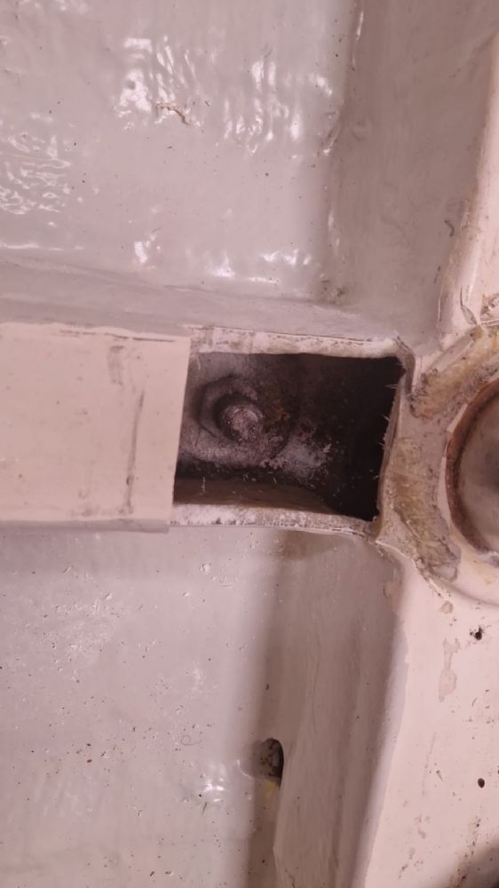
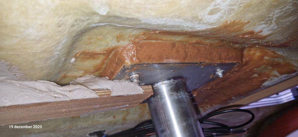
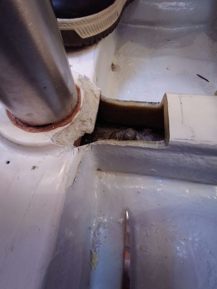
Recently we
opened up a bit more of the polyester and we could se more of the structure.
the roof the pole is bolted on and no cracks anywhere uploads/7095/open_2.pdf
In pdf
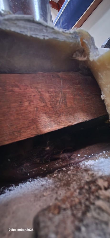
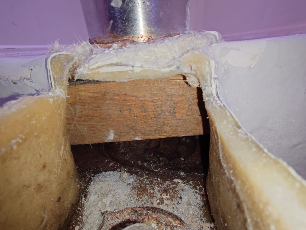
kom_4 you can see that the gap under the beam, above the beam there is some GRP
in the shape of a square recess that holds the RVS pole above the wooden beam. Since
wood can bent I believe this beam went down 3 to 6 millimeters wat results in
extra stress on the GRP.
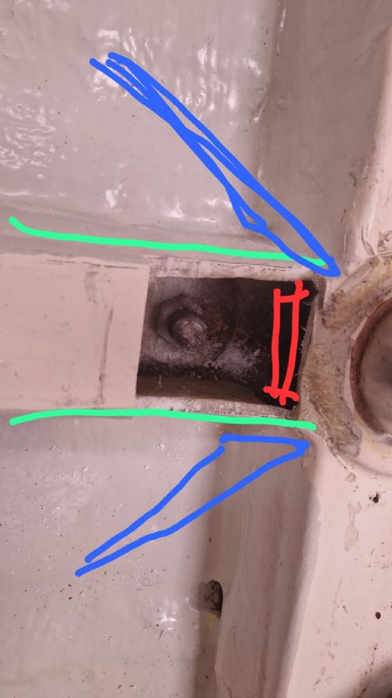
Im
planning to reinforce the square resess (bleu arrow) . By ending more GRP to it
so I can increase the strength of the recess and connect it better to the wood.
Since Im building this GRP up anyway Im going to pack the wood as good as possible
and create a soled connection between the wood and the GRP structure of the
boat (red arrow).
The last
part of the repair will be reinforcing the length wise springer with wooden slats wrapped in polyester (the
green lines). Im not sure yet if Im going to do this on the in or outside of
the springer. On the inside its hard to get a clean bonding surface. But I can connect
it to my first repair (red square) what will give a strong connection. On the
outside it will be a bit easier but wont look nice.
To help this 23
year old boat with its injury Im planning to give it a bit more extra strength.
In blue lines I tried to show how Im planning to add to GRP (wood inside) triangles that will make a connection between
the square recess and the hull to add some extra strength. Edited by on y va - 21 December 2025 at 19:59 |
|
|
|
|
on y va
Sub Lieutenant
Joined: 28 April 2021 Location: Brabant Status: Offline Points: 6 |
Post Options
Thanks(0)
Quote Reply
Posted: 21 December 2025 at 20:16 |
|
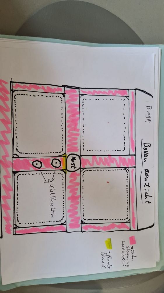
Im not
starting a monologue but Im not afraid to add some extra strength since I found
pictures of other 311s that have more springers than mine.
and below is mine. seems like some have extra springers (red lines)?
Does anyone have pictures of there hanse 311 or
312 without floorboards? |
|
|
|
|
sgrhma2
Captain 

Joined: 20 November 2021 Location: Northern Irelan Status: Offline Points: 271 |
Post Options
Thanks(1)
Quote Reply
Posted: 21 December 2025 at 22:27 |
|
Having looked at you photos, I think you may be unduly worried. The grey paint is actually flow coat, which is just resin that is painted on to cover and tidy up the layup and tabs that the floor frame is bonded in with. It has no glass fibre in it to provide reinforcement and is just decorative. Looking at all the other sub floor recesses, there is absolutely no evidence of stress cracks, which would suggest the boat hasnt been grounded severely which gives stress cracking or failure usually at the front of the keel attachment where it will have been pulled down and at the back where the rear of the keel is pushed up into the hull. The areas in your photos show absolutely no evidence of this. If it has been grounded that hard there should also be evidence on the keel itself.
The wood underneath the frame has obviously never been bonded to the inner frame and as such isnt really providing much in the way of support for the GRP frame the mast sits on. What the wood is for, I suspect is to support the inner moulding at approximately the correct height before the mast support pole is fitted and the frame then bonded in with GRP tabs. To do this the frame with most of the furniture and engine is set in place and probably tabbed in place at the stern of the boat and around the engine. The deck is then placed and bonded onto the hull. Once the deck is fully attached, the mast support pole is fitted by jacking between the inner frame (which is still not bonded to the hull and is sitting on the wooden beam) and the inside of the deck. This pushes the frame down sufficiently, bending the beam slightly, to insert the mast support heel into the recess in the floor frame and the reinforcement in the deck for the mast. The bolts you see I would expect are the same ones that locate the deck mounted mast fitting. Once the pole is in place, the jack is removed, the GRP supported by the beam, push firmly upwards against the mast support pole. It is at this point that the front of the internal frame is then tabbed fully to the hull, ensuring a perfect fit for the mast support pole and spreading the mast loads across the hull through the internal frame and the GRP tabbing bonding it to the hull. From this point onwards the wooden beam is irrelevant, it isnt doing anything except baffling owners that find it. The GRP frame is significantly stronger and stiffer than the wooden beam. Its only still there because its too difficult to remove it once its done its job of supporting the frame and mast pole during production. As for the cracks at the base of the pole, these appear to be only in the the gelcoat of the frame, not in the GRP matrix. Like flow coat, gelcoat is only resin and has no reinforcement in it. The gelcoat cracks I would expect occurred when the frame was being jacked down to fit the pole and dont appear to be anything to worry about. You do now have a bit of work to do repairing where youve opened the frame up a bit, but its only minor and as you said should be done using glass and epoxy. I hope this was useful and if you want to discuss further feel free to pm me. Simon
|
|
|
|
|
on y va
Sub Lieutenant
Joined: 28 April 2021 Location: Brabant Status: Offline Points: 6 |
Post Options
Thanks(0)
Quote Reply
Posted: 28 December 2025 at 18:27 |
|
Hey Simon,
Thanks for
your explanation, this makes the situation a lot clearer. Today I have stripped
away the delaminated and shattered GRP to a point where it is somewhat hard.
I'm afraid the cracks at the base of the pole are a bit bigger than we hoped. What I found was this strange build-up of grp, gelcoat, grp and gelcoat. What I found was this strange build-up of grp, gelcoat, grp and gelcoat. The piece we have taken out shows this well. I cant imagine this is good for the strength.
Hopefully I
can get some more advice about this repair? |
|
|
|
|
Post Reply
|
|
| Tweet |
| Forum Jump | Forum Permissions You cannot post new topics in this forum You cannot reply to topics in this forum You cannot delete your posts in this forum You cannot edit your posts in this forum You cannot create polls in this forum You cannot vote in polls in this forum |
|
Links : www.hanseyachts.co.uk www.hanseyachts.com www.fjordboats.co.uk www.dehler.co.uk www.varianta.co.uk |


 Topic Options